REGENT Seaglider CFD Analysis with Flow360
REGENT, a pioneer of zero-emission regional coastal transportation, has teamed up with Flexcompute to develop their revolutionary floating, foiling and flying “seagliders”. By leveraging our game-changing CFD solver, Flow360, REGENT engineers are able to simulate complex flow physics with greater confidence and in record time.


Introduction
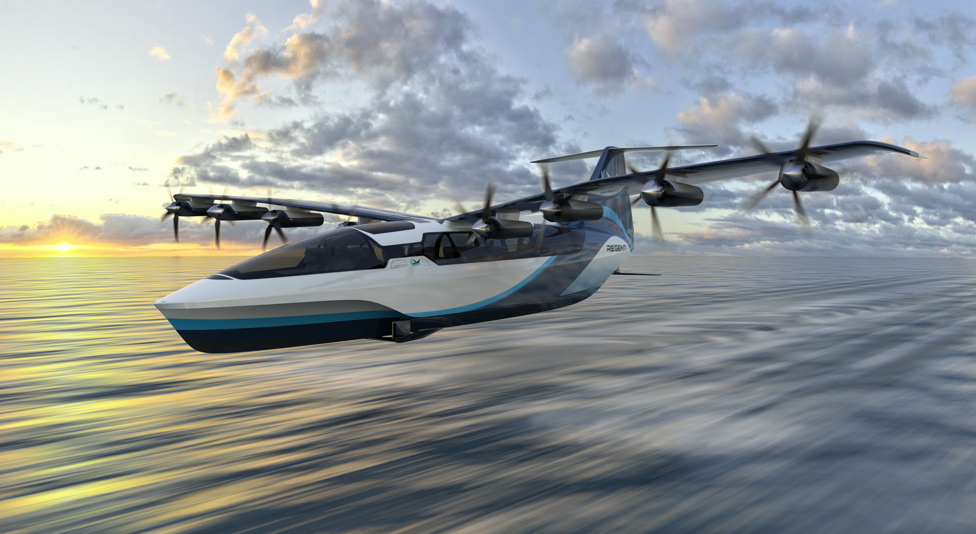
REGENT, a North Kingstown, Rhode Island based company, is designing and building “seagliders”. REGENT’s seaglider is a fully electric vehicle that utilizes a blown wing and hydrofoils for takeoff from the water, instead of gas powered engines and a hull used by traditional seaplanes. Once airborne, the seaglider flies within a wing span of the water surface as a wing-in-ground-effect to take advantage of the cushion of air that forms between the vehicle and the water surface, improving efficiency. Such an efficient commuter transport will be greatly beneficial for passengers traveling between coastal cities. Seagliders are a much more efficient alternative to traditional hopper flights and a much faster alternative to traditional ferry routes.
By using electric power instead of fossil fuels, REGENT can efficiently distribute power to many motors along the wing. This not only increases the safety by adding redundancy to the propulsion system but also allows for effective blown-wing technologies. By blowing the propeller wash over as much of the wing as possible, seagliders can takeoff at much lower speeds than conventional seaplanes.
Developing such a concept combining many new technologies is a very ambitious endeavor. To develop their revolutionary floating, foiling, flying seagliders, REGENT is using computational fluid dynamics (CFD) simulations to better assess safety, performance, control, and passenger comfort criteria. By leveraging the Flow360 CFD solver at various stages of the design process, REGENT engineers are able to efficiently analyze design iterations with greater confidence.
Flexcompute’s Flow360 CFD solver ushers in a new era for engineers developing high accuracy flow solutions. By rewriting the solver from scratch using 21st century numerical methods and combining it with the latest computing technologies, Flow360 can achieve unprecedented speeds and increased accuracy. Flow360 users can do in minutes what would previously take hours or even days. The cloud computing environment scales for extremely large simulations and enables parallel throughput of extensive case matrices, all at a reduced cost.
Faster, more accurate CFD enables better development
The original seaglider concept was sketched on a napkin and quickly progressed through low-fidelity performance validations. Then detailed design work on a scaled demonstrator (Squire) was followed by coupled CFD and wind tunnel testing, leading to Squire’s successful first flight. Building on this successful design process, REGENT is continuing to emphasize both digital and physical testing for their first full scale human piloted vehicle, Paladin.
With regards to safety, the company is hyper focused on meeting or exceeding the same risk-based safety levels that are applicable to passenger aircraft. While flying in ground effect, the seaglider’s aerodynamics are important for precise flight control capability, passenger comfort (acoustics, vibration) and safety. Addressing these design challenges requires leveraging a world class aerodynamics group using state-of-the-art simulation technologies. A revolutionary CFD solver like Flow360 provides a distinct advantage for REGENT’s engineering staff, enabling them to analyze more complex flight conditions and flow physics in significantly less time.
Rotor modeling with blade element theory and moving reference frames are fast and efficient simulation techniques for initial design iterations and sizing studies, but when designing blown wings, a fully time-accurate, scale-resolving simulation with rotating mesh is preferred. The resulting pressures extracted can then be assessed by the structures team to digitally validate designs over many flight conditions before proceeding to physical testing. This enhances safety of the final product by understanding rotor-wing interactions before ever stepping into a wind tunnel.
To ensure accuracy and build correlations involving digital simulation results, REGENT is validating CFD methodologies with wind tunnel tests of a full-scale segment of their blown wing. Instrumentation onboard the test article reads surface static pressures, motor torque and power, as well as all body forces and moments. By correlating the same geometry and operating conditions both in the wind tunnel and in CFD, REGENT can increase certainty in digital designs and achieve success with its first prototype builds.
Evaluating test requirements with CFD
Preemptive CFD simulations of the wind tunnel setup can provide additional flow insights prior to the physical test campaign. Simulating the blown wing test article operating within the wind tunnel helps to reduce risk associated with the apparatus design and to inform the envisioned run matrix. Accurate and reliable CFD is used to confirm certain assumptions and answer key questions:
- This blown wing configuration is designed to generate more lift than a conventional wing of similar size. Because of this extra lift, the test stand (i.e., structural supports holding the test article) requires careful design considerations to ensure that it can handle the forces and moments generated during testing with safety margins applied.
- Testing could potentially result in significant vibrational loads and unexpected twisting/bending due to the complex flow physics induced by the model. Simulation allows for the recognition of and evaluation of unexpected response behaviors that could present safety concerns if unaccounted for.
- The test stand itself may also induce unfavorable flow conditions that could affect the quality of wind tunnel measurements. For example, the support structures and measurement equipment may disrupt the flow field near critical regions of the test article, potentially distorting measurement.
- A full-scale model poses additional challenges as its size relative to the wind tunnel test section could influence the intended operating conditions. Some of the desired test points may not be achievable due to blockages imposed by the full-scale model. The surrounding wind tunnel geometry may even affect sensitive measurements at the wing section.
Simulating the blown wing wind tunnel test
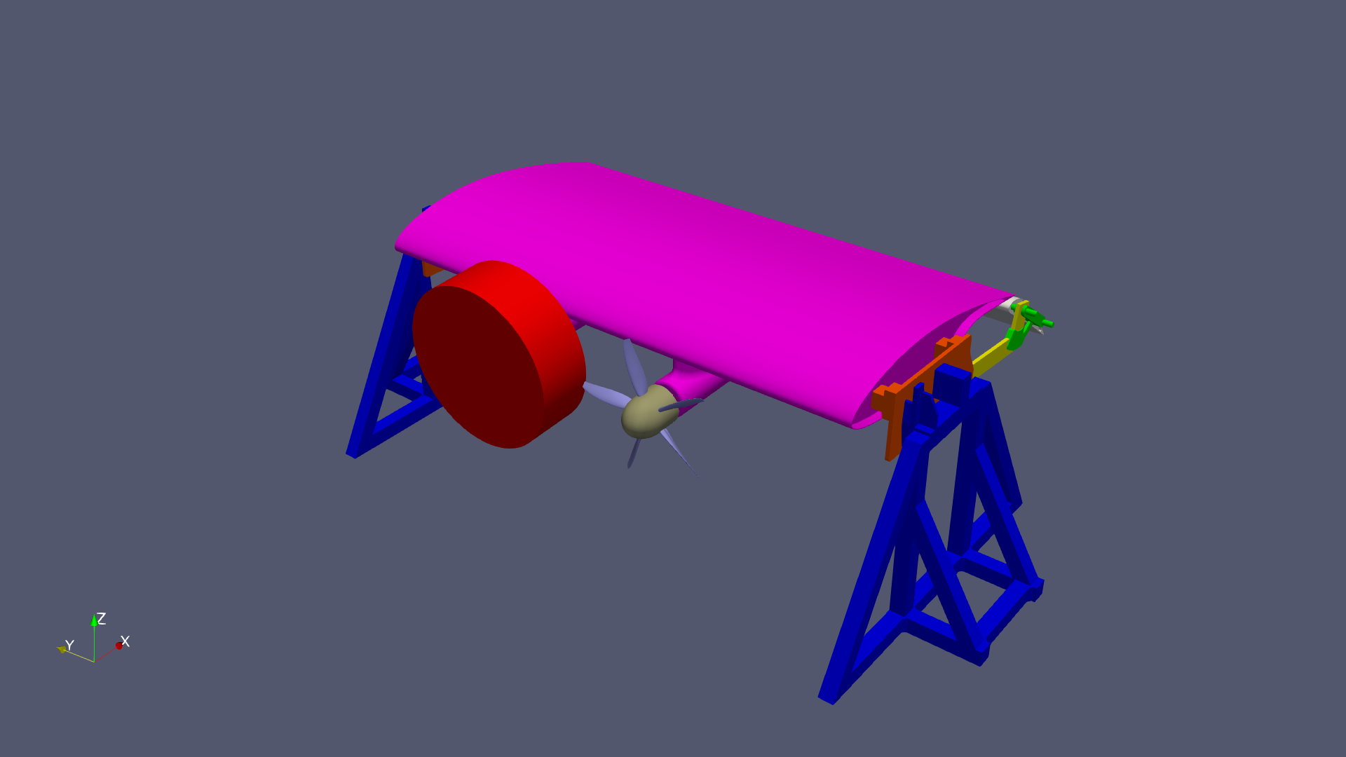
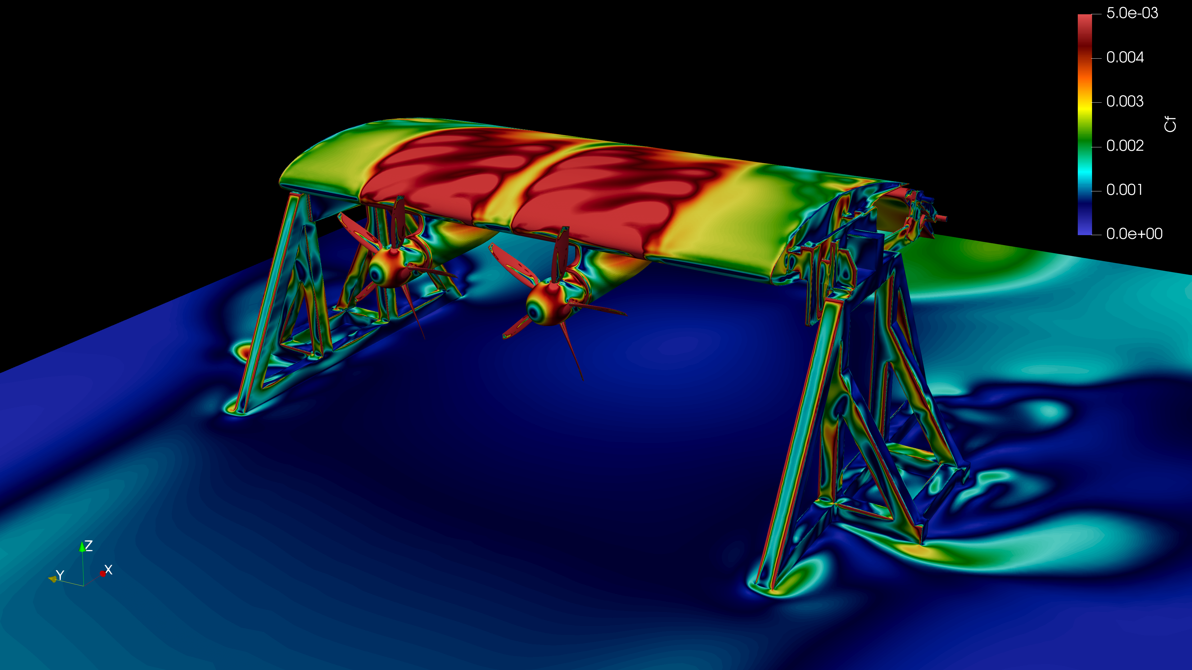
To address the above wind tunnel test considerations and develop digital-physical correlations, REGENT engineers are simulating the test configuration with Flow360. As seen in Figure 2 the test article itself includes structural supports, mechanisms for flap deflections, and two rotating propellers. Additionally, the entire wind tunnel is modeled including test section details, plenum and diffuser with turning vanes (see Figure 3).

The analysis strategy targets a series of time-accurate delayed detached eddy simulations (DDES) at various operating conditions. An unstructured mixed element mesh is generated with y+ ≤ 1 wall spacings throughout and sliding interfaces enclosing the propeller rotational domains. In total, about 4M surface elements and more than 150M volume elements comprise the CFD model.
To most efficiently simulate this complex configuration, REGENT first runs steady-state cases to initialize the flow field. Then, from these initialized conditions, a cascade of transient DDES cases are run spanning more than 25 propeller rotations. The time-accurate DDES simulations are sequentially refined to as little as 1° of propeller rotation per time step. Both the extended time period and small time step size create an accurate representation of the flow physics involved.
Flow360’s state-of-the-art performance allows REGENT to simulate these large and complex models in less than 6 hours and at a lower cost than comparable CFD solvers. The speed and accuracy provided enables engineers to make decisions based on flow insights gained from challenging problems.
Conclusion
By leveraging Flow360’s unprecedented speed and accuracy, REGENT engineers are able to simulate complex flows with confidence and in record time. The resulting flow insights allow for confirming assumptions, preemptively addressing concerns, and preparing for successful test campaigns.
REGENT is just beginning to scratch the surface of possibilities for next generation vehicles. More design concepts, wind tunnel models, and flight testing campaigns are on the horizon. Flow360 continues to expand capabilities, improve robustness, and dramatically increase performance. The solver is purpose-built and developed to empower engineers in all aspects of the design process.
In our next article we will investigate how CFD results compare to physical tests in the wind tunnel and share lessons learned about the effective application of CFD. Stay tuned.
If you’d like to learn more about CFD simulations, how to optimize them, or how to reduce your simulation time from weeks or days to hours or minutes, stop by our website at flexcompute.com or follow us on LinkedIn.
A PDF version of this article is available for download here.


