A mirror with no mirror in it
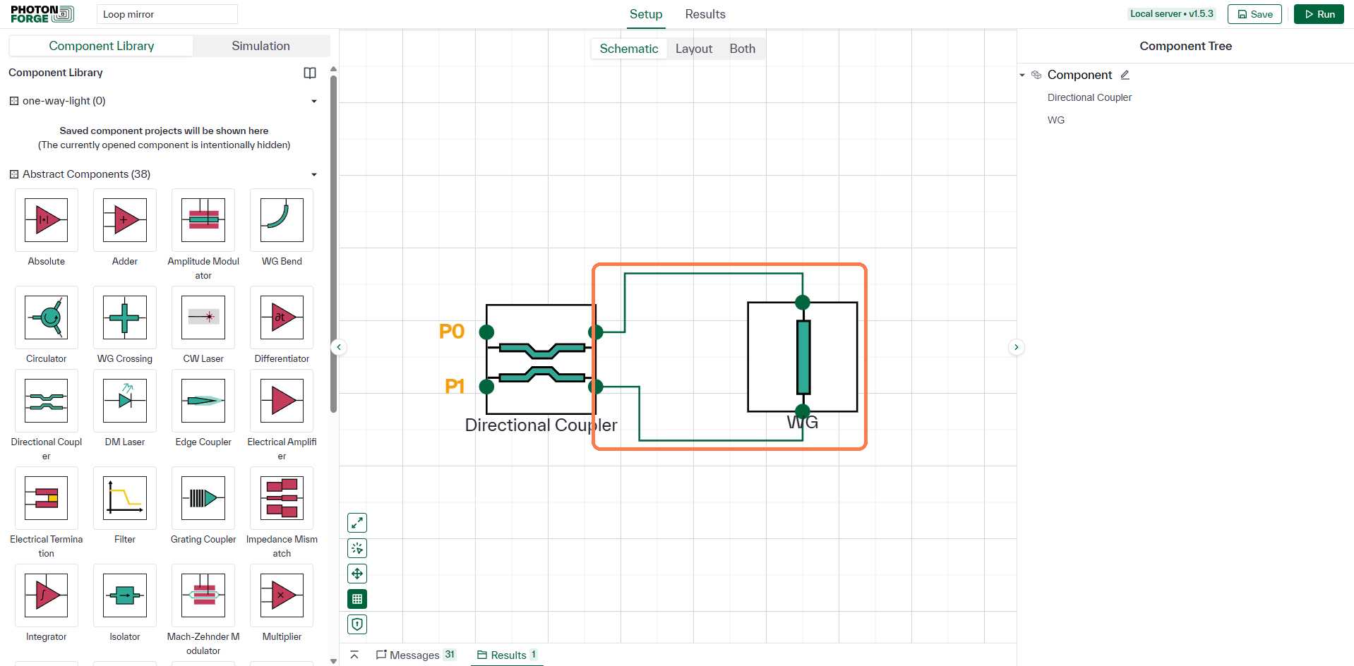
Take a Directional Coupler and connect its two right-hand ports, P2 to P3, with a WG. A field entering P0 is split into two counter‑propagating components that traverse the identical loop, so both accumulate the same propagation phase. Back at the coupler, each component returning to P0 has made one bar transit and one cross transit, so the two are identical in amplitude and phase and interfere constructively. At P1 one component has made two bar transits and the other two cross transits; each cross transit contributes the coupler's −90°, so those two arrive 180° apart and interfere destructively. Assign P0 and P1 as circuit ports.
This is a Sagnac loop, and it is worth noting what it is not: the loop is not a cavity. Each component makes a single transit rather than recirculating, so no field builds up and the structure is non‑resonant.
One number sets the reflectivity
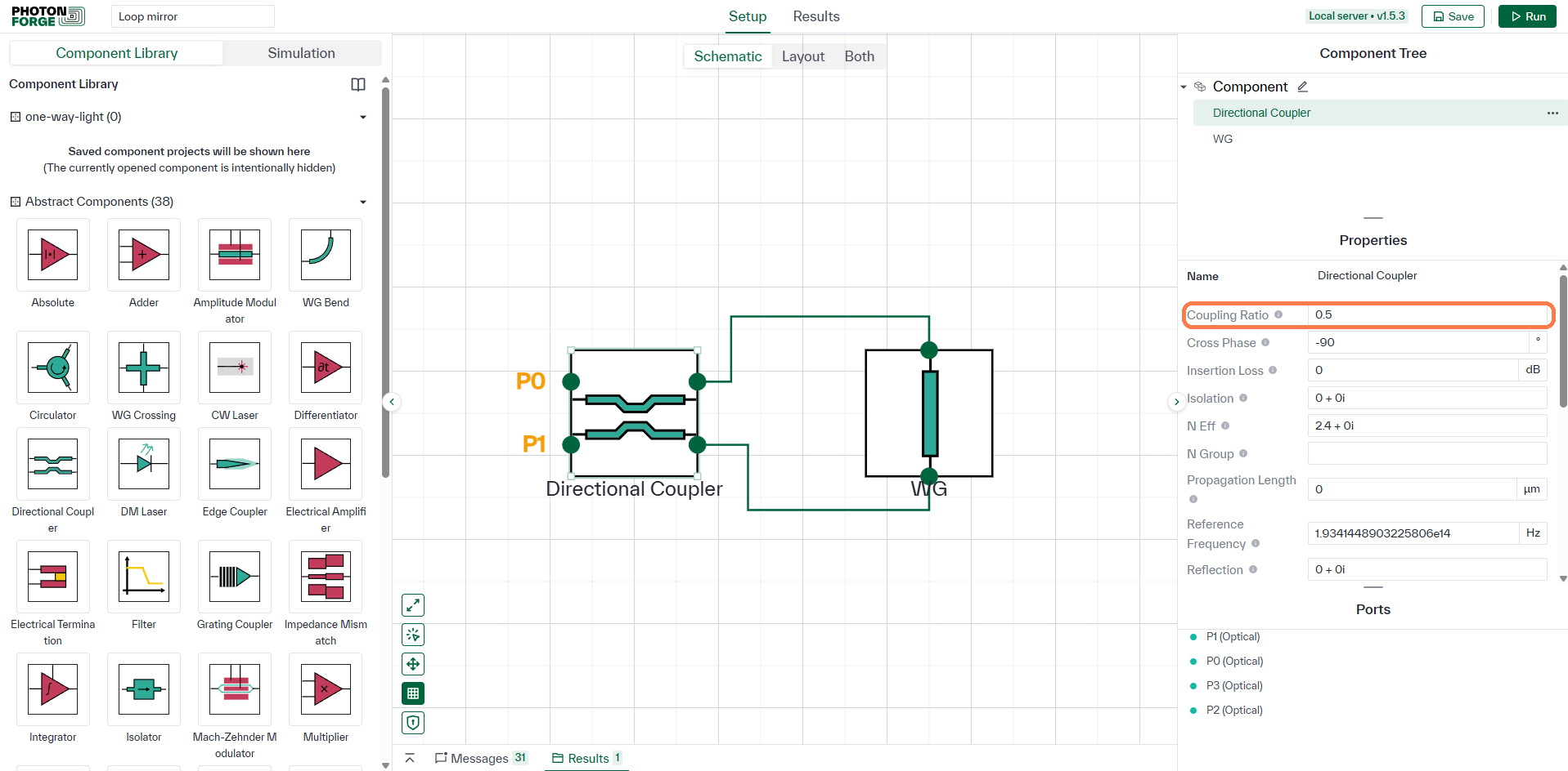
Leave the coupler at Coupling Ratio = 0.5 to start. This single number decides everything about the mirror, because it sets how the two counter‑propagating halves are weighted when they recombine. Cross Phase stays at its default −90°, which is what steers the recombined light back into the input port rather than the other one.
The length does not matter
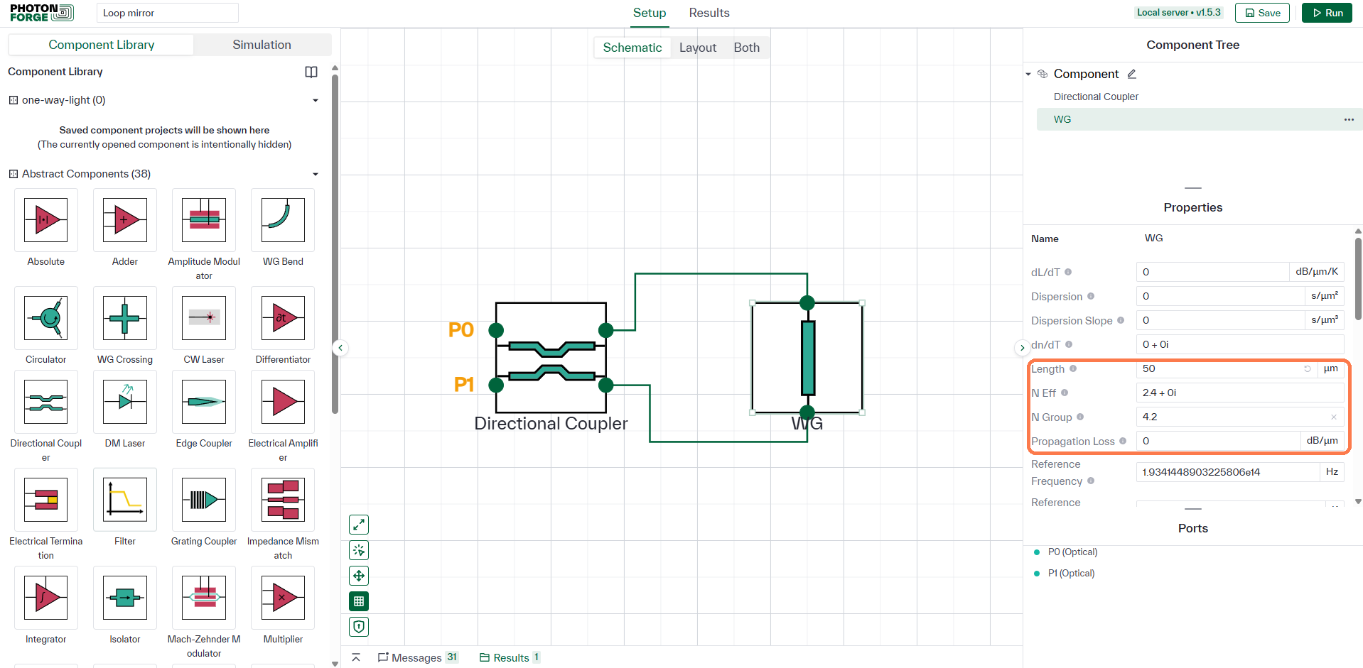
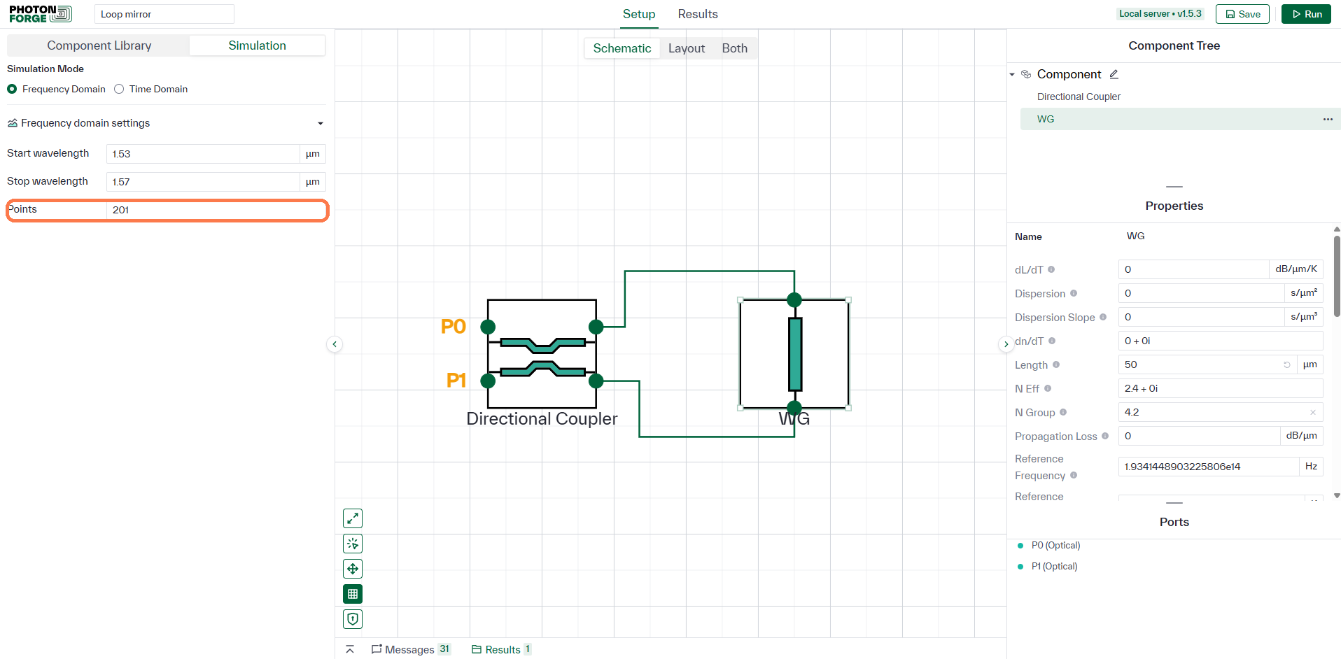
Set the loop waveguide to Length 50 µm, N Eff 2.4, N Group 4.2 and Propagation Loss 0. Now the interesting part: change that length to anything you like and the result will not move. Both halves cover the identical path, so whatever phase one picks up the other picks up too, and it cancels on recombination.
Why that matters: a device whose behaviour does not depend on an optical path length is inherently broadband. This mirror works at every wavelength you can send through it.
A coarse sweep is plenty
Sweep 1.53 to 1.57 µm with 201 points. Because nothing here resonates there are no narrow features to step over, and no reason to pay for a fine grid. What sets the point count is the width of the sweep divided by the narrowest feature you need to resolve, so a wider sweep over the same device costs proportionally more points.
All of it comes back
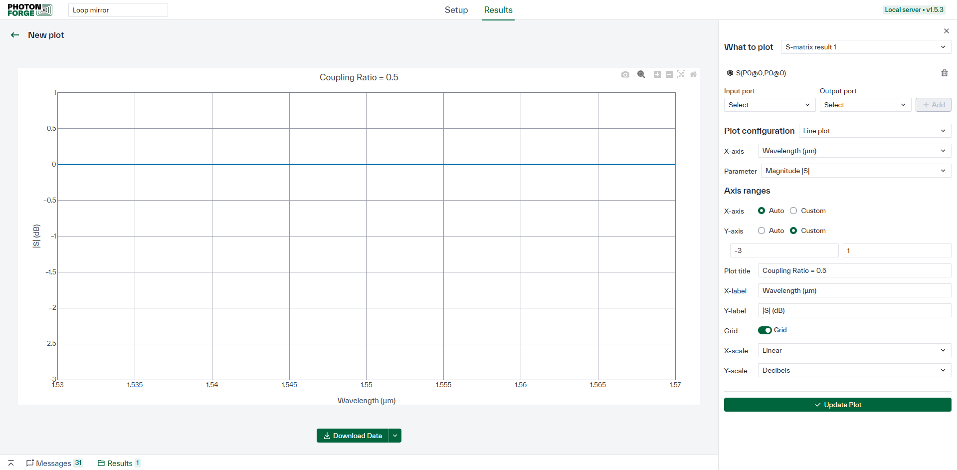
Run, then plot the reflection: input port P0, and output port P0 as well. It sits at 0.00 dB flat across the whole band. Every photon that went in comes back out the same port, from a device with no mirror, no coating and no facet anywhere in it.
On the missing second trace: transmission to P1 is not merely small here, it is exactly zero, so it cannot be drawn on a decibel axis at all. That is the cleanest possible evidence that the two halves cancel perfectly at the other port.
Turn the dial, split the light
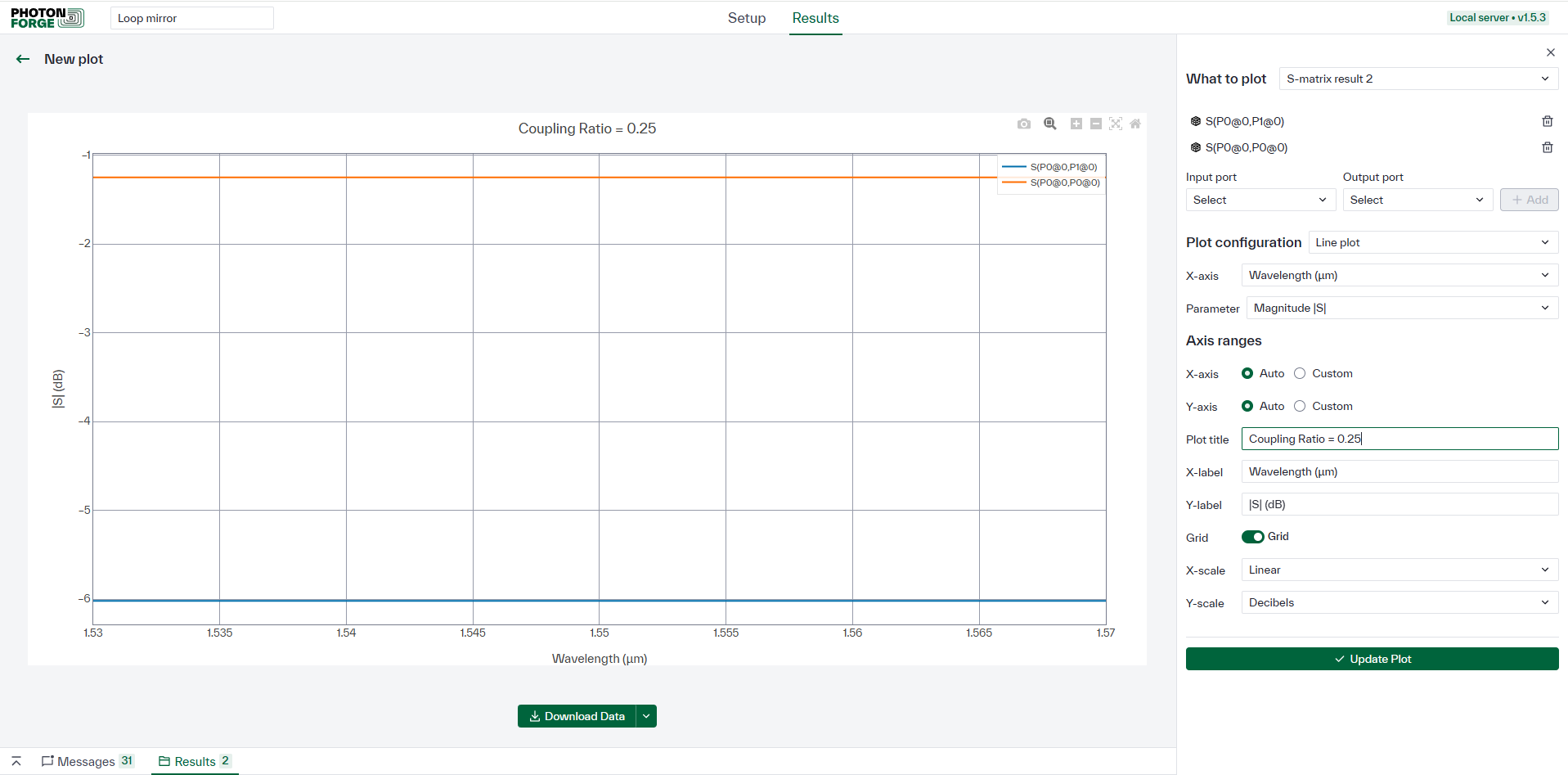
Set the Coupling Ratio to 0.25 and run again, this time plotting reflection and transmission together. Now 75% comes back (−1.25 dB) and 25% goes through (−6.02 dB). Nothing is lost: the coupler simply decides how the returning light divides between the two ports, and the two figures add back up to one.
Reflectivity you can predict
Save a plot at 0.25, 0.50 and 0.75. Working the two interference terms through gives closed forms that the solver reproduces to five decimal places:

Both expressions are unchanged under κ → 1 − κ, which is why 0.25 and 0.75 give identical results: only the imbalance of the split matters, not which output the coupler favours.
The mirror does not always win. R exceeds T only for κ between (2 − √2)/4 ≈ 0.146 and (2 + √2)/4 ≈ 0.854, where R = T = 0.5. Outside that window most of the light leaves by P1 instead: at κ = 0.05, R is 19% against T at 81%.

Does it survive a real coupler?
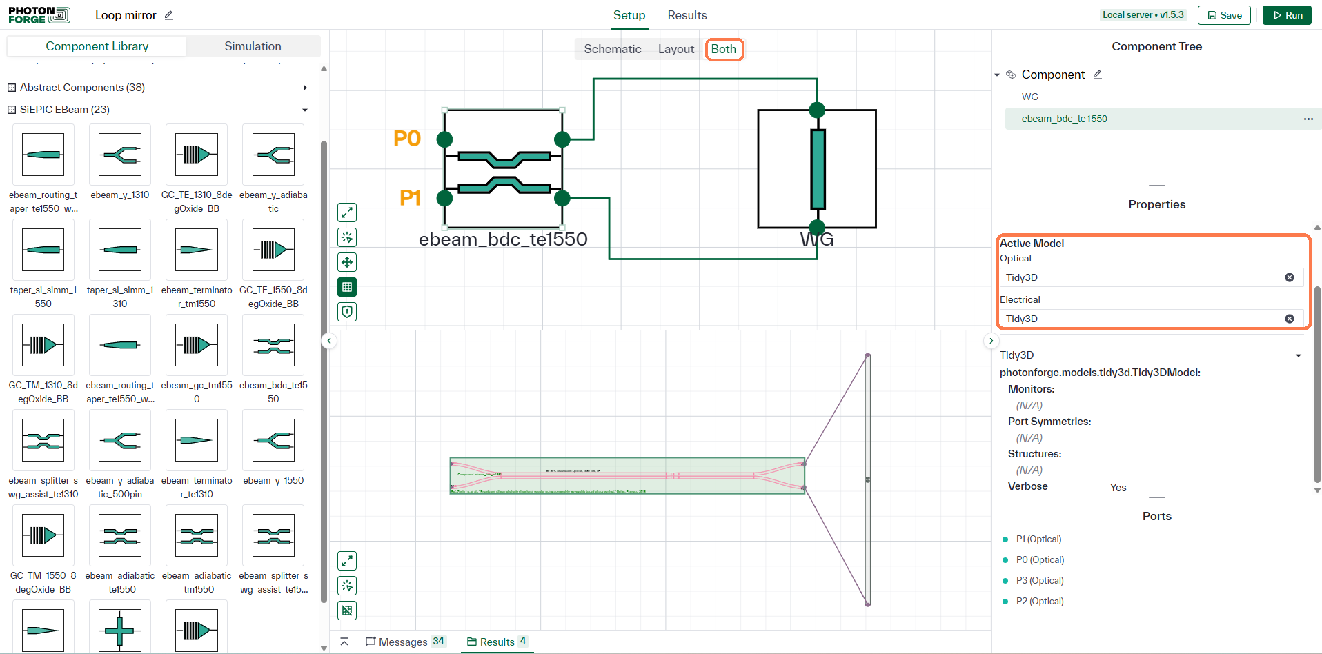
Everything so far assumed a perfectly ideal split. Replace the abstract coupler with ebeam_bdc_te1550, a broadband directional coupler from the SiEPIC EBeam PDK, and the mirror is suddenly made of something you could send to a foundry. Its Active Model is Tidy3D, because unlike the abstract part this component carries real layout. Switch the canvas to Both to see the schematic above and that layout below.
PhotonForge sets up the simulation for you
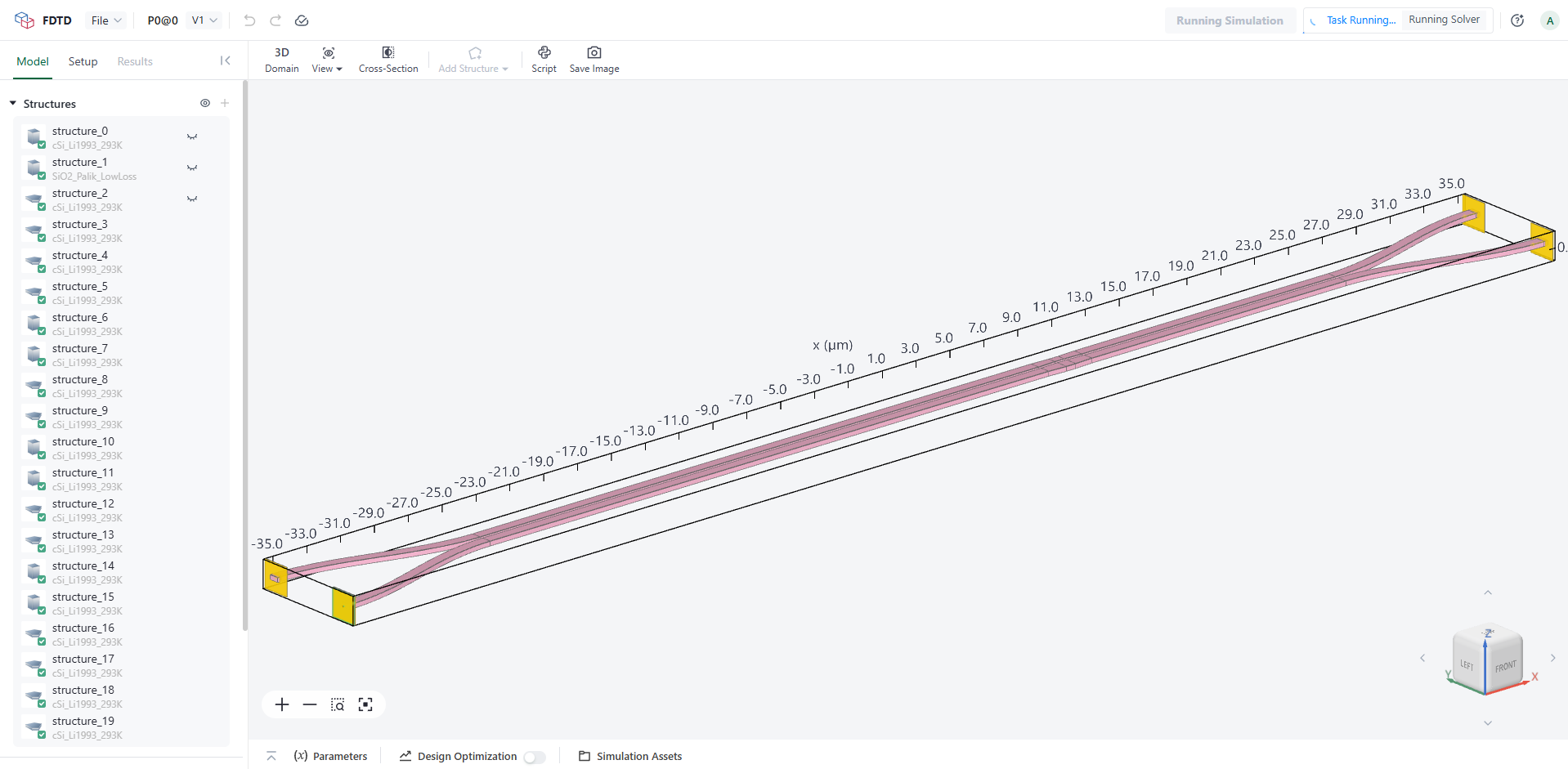
Click Run. PhotonForge sees that the coupler needs an S‑matrix, builds the 3D structure from the PDK layout and process stack, and submits Tidy3D FDTD simulations automatically, one per input port, with sources and monitors already in place. This coupler is roughly 70 µm long and about twenty separate structures, and none of it had to be drawn by hand. Results are cached, so the next run reuses them at no cost.
Still a mirror
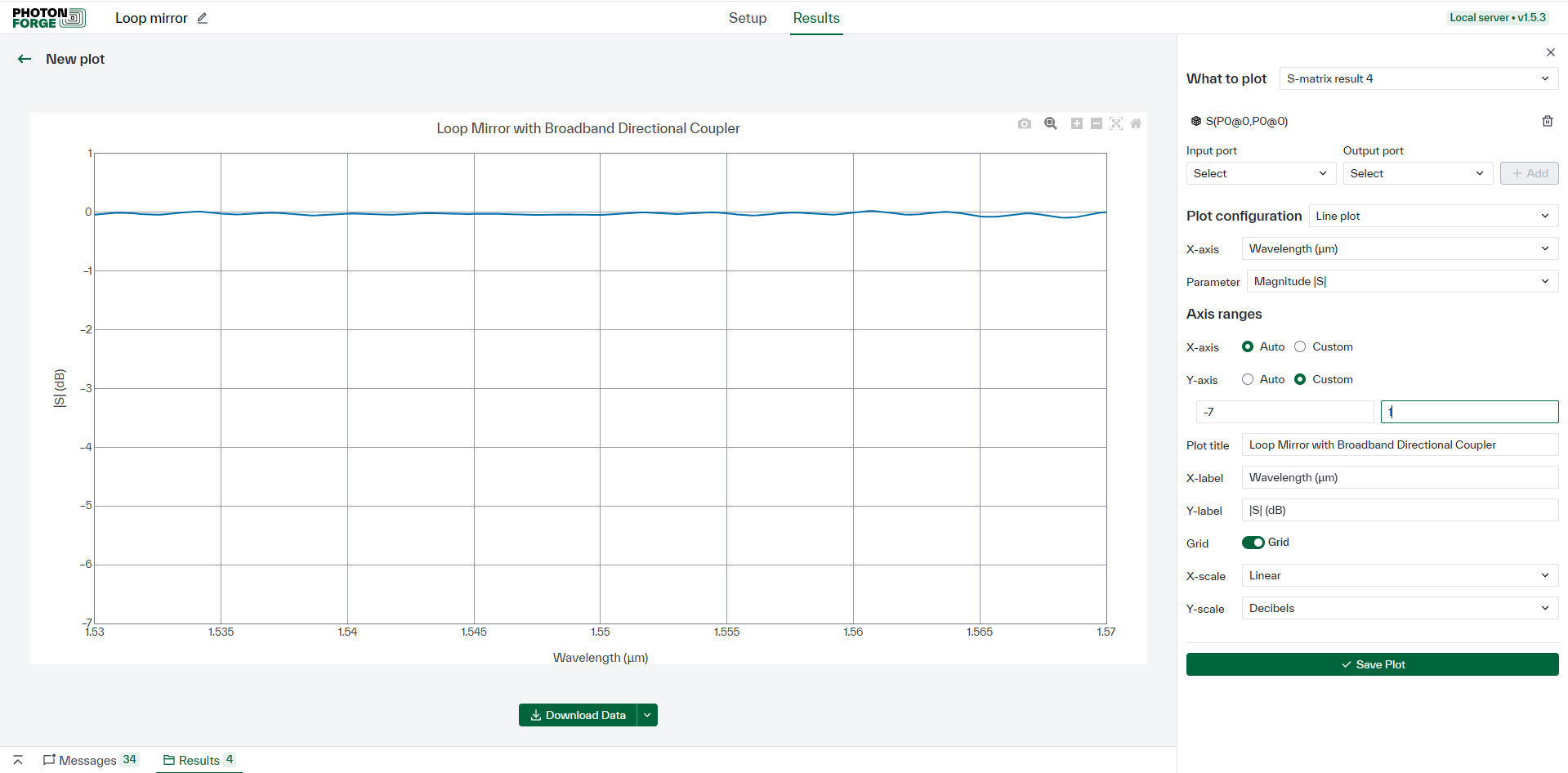
The reflection holds within about a tenth of a decibel of 0 dB right across the band, with only a gentle ripple where the real device departs from an exact 50/50 split. The design survives contact with a fabricable part.
Why this coupler: the answer is in its name. A plain directional coupler splits differently at different wavelengths, so 4κ(1 − κ) would sag toward the edges of the band and the mirror would start leaking. A broadband coupler holds its split, which is exactly the property a broadband mirror needs.
Getting out of the way
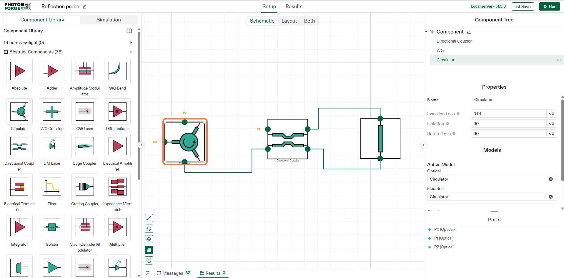
A reflection that comes straight back down the input is awkward to measure: you cannot stand in its path. A Circulator fixes that by passing light one way around its three ports. In at P0, out at P1 to the mirror, back into P1, and out at P2. Assign P0 and P2 as the circuit ports and the reflection arrives at a port of its own, reading −0.02 dB: the entire reflection, less two trips through the circulator.
A component that only works one way
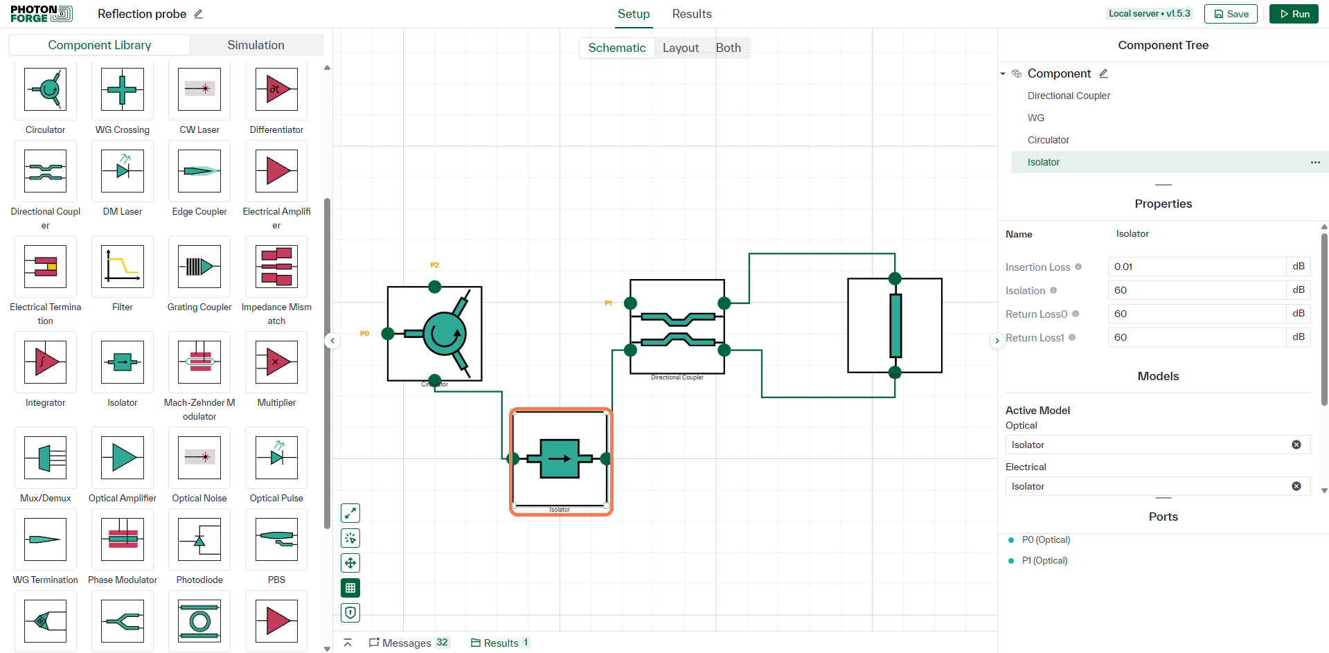
Drop an Isolator between the circulator and the mirror, with its P0 facing the circulator. The component transmits P0 → P1 at its Insertion Loss of 0.01 dB and attenuates the reverse direction, P1 → P0, by its Isolation of 60 dB. The outgoing field therefore travels in the low‑loss direction. The field returning from the mirror enters at P1 and must leave at P0, which is the attenuated direction, so it takes the full 60 dB.
Why anyone cares: reflections that find their way back into a laser destabilise it. An isolator sitting in front of the laser is the standard defence, and this circuit is that arrangement in miniature.
One component, fifty decibels
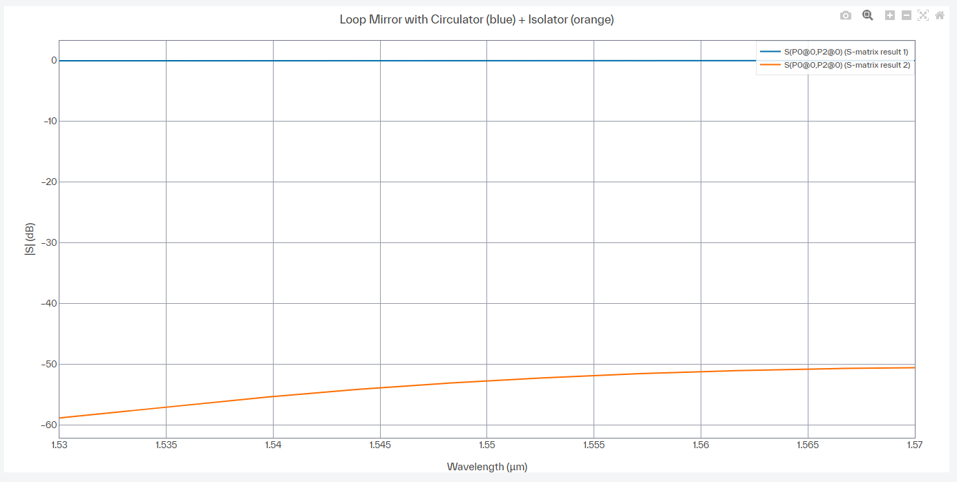
Plot the two runs together. Without the isolator the reflection arrives essentially intact; with it, the very same reflection falls to between about 50 and 60 dB below. Nothing else in the circuit changed. The mirror is still a perfect mirror and the light still reaches it. It simply cannot get back.
Why that floor is not flat. Fifty decibels down you are no longer measuring a single path. What reaches the monitor is the coherent sum of several comparable leakage terms: the circulator's finite isolation, the isolator's finite isolation, and the return losses of both. Only some of those terms travel through the loop, so they carry a wavelength‑dependent phase and the sum ripples. Raise the isolator's Isolation to an unphysical 200 dB and what remains is a perfectly flat −54 dB, which is the circulator leaking straight from P0 to P2 without ever seeing the mirror.