Tidy3D
Case studies
Wind tunnels have long been a cornerstone of aerospace engineering, providing direct measurements of forces and moments on physical models, with real-world fluid dynamics faithfully reproduced by nature itself. However, full-scale, production-ready models are often impractical to test—both due to cost and because, by that stage, it’s too late to meaningfully impact the design. While a well-executed wind tunnel campaign yields invaluable data, modern Computational Fluid Dynamics (CFD) offers powerful and complementary advantages.
With a tool like Flexcompute’s Flow360, we can simulate full-scale, state-of-the-art geometries quickly and accurately. Built for GPU-native performance, Flow360 enables us to run highly complex simulations in a matter of minutes—dramatically accelerating our design cycles. This speed and robustness allow for rapid result comparisons, deeper design confidence, and the creation of high-value aerodynamic performance databases critical for our flight controls and simulation teams.
Beyond forces and moments, CFD unlocks rich insights into the underlying physics of flight, providing a level of flow visualization that few other methods can match
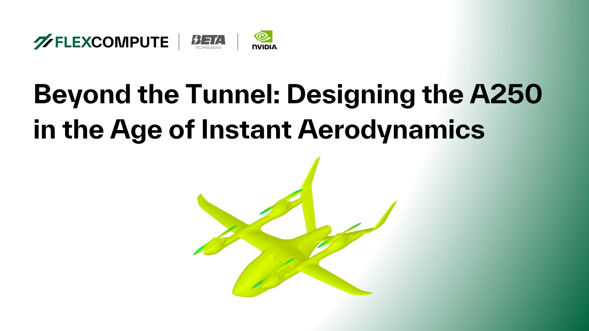
Figure 1: BETA Technologies subscale A250 model

As a vertical takeoff and landing (VTOL) vehicle, the ALIA A250 must transition seamlessly between vertical and horizontal flight. This shift—from thrust-borne to wing-borne flight and back—creates complex aerodynamic interactions. Wake flows from the lifting propellers wash over the wings and impact downstream propellers, making it critical to capture and understand these effects with our computational tools.
Wind tunnel testing clearly revealed aerodynamic interference between the lift propellers and the airframe, but it couldn’t fully visualize the underlying flow phenomena in the detail we wanted. By replicating key test points in CFD, we unlocked a deeper understanding of the flow physics—and demonstrated Flow360’s ability to accurately reproduce aerodynamic interactions and their impact on forces and moments.
Furthermore, CFD allows us to run the test points at full-scale Reynolds numbers, with production lift propellers and production geometry.
Figure 3: Time history of force and moment breakdown on various A250 components.

By breaking down forces and moments component by component, tracking their evolution over time as the propellers rotate, and combining this with:
● Surface skin friction visualizations
● Streamline flow data
● Q-criterion isosurfaces (to map vortex and downwash behavior)
We gain insights into some of the most aerodynamically interesting parts of the flight envelope, with much of the post-processing taken care of directly within Flow360.
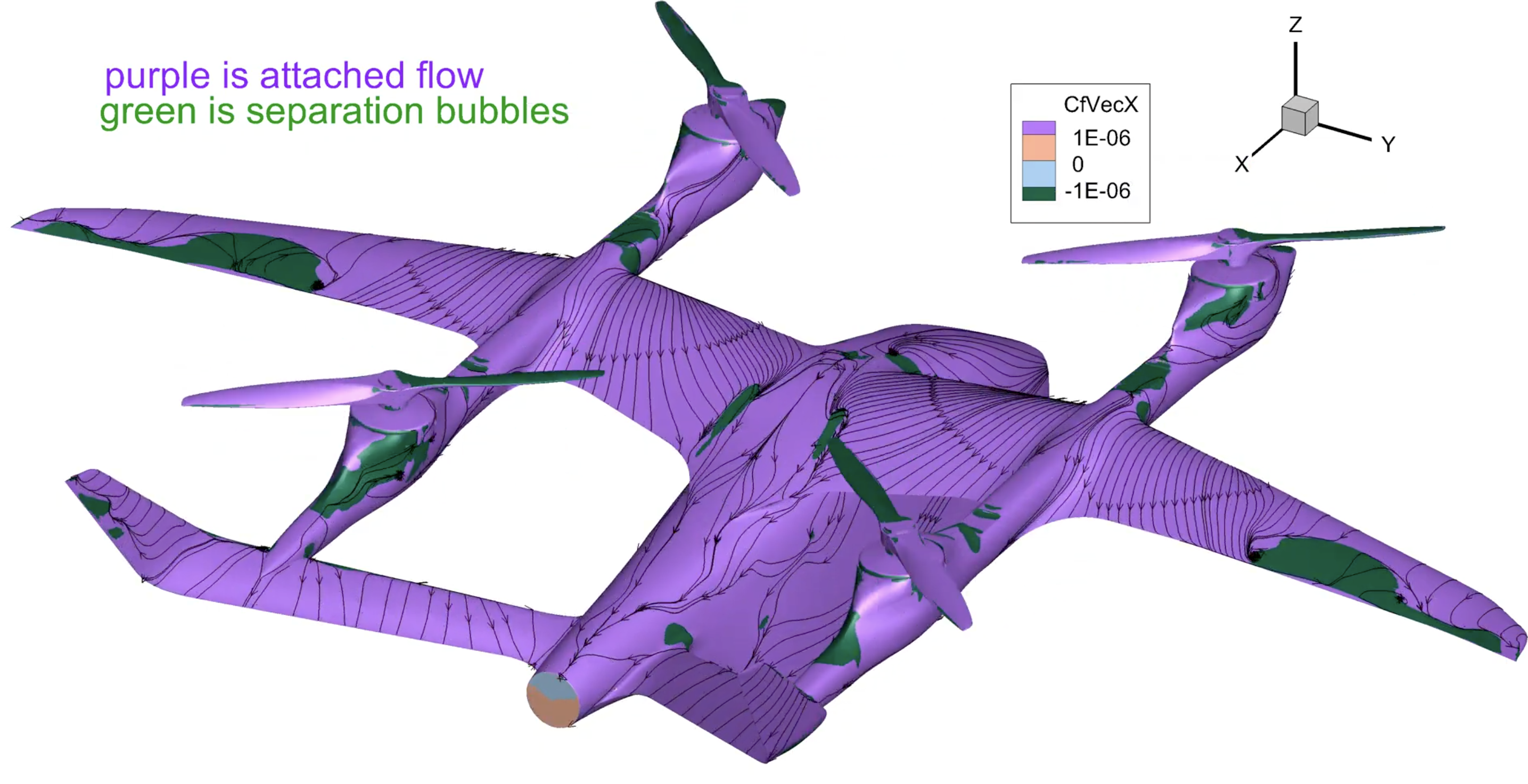
Figure 4: Surface streamlines showing recirculation regions
Fig-5: Snapshot of Q-criterion isosurface revealing wake shedding

What Makes These Simulations So Challenging?
These CFD simulations are far from simple. They feature:
● Fast-spinning propellers, requiring small time steps to capture transient flow accurately
● Wake propagation, needing long simulation times to stabilize
● Highly refined mesh zones, particularly between interacting components, leading to massive mesh sizes—up to 119 million nodes
● Stringent accuracy demands, including many subiterations per time step to reach convergence by at least two orders of magnitude
● Advanced turbulence modeling, using the latest Spalart-Allmaras DDES implementation combined with low numerical dissipation algorithms
Fig-6: Slice through y=0 Symmetry plane showing volume mesh refinement regions.

Performance at the Cutting Edge
Flow360 enables us to run fully time-accurate DDES simulations with 119 million nodes—achieving under 7 minutes per propeller revolution using just 8 NVIDIA B-200 GPUs on Flexcompute hardware. That’s the speed and fidelity needed to drive real design decisions.
That’s speed and fidelity we can build on.
Why It Matters
Running these simulations early allows us to:
- Avoid costly redesigns
- Accelerate iteration cycles
- Deliver better, safer aircraft faster than ever before
With this level of insight, we can detect aerodynamic issues before a single part is manufacture, fixing them early in design or addressing them through flight control logic long before first flight. This predictive capability reduces rework, cuts cost and keeps us on schedule. CFD isn’t just a support tool anymore. It’s a core enabler of the next generation of flight.
Introduction
In 2024, Flexcompute participated in the AutoCFD4 workshop, where we presented our highly accurate and fast results for the DrivAer model. The AutoCFD4 workshop is an international forum for researchers and practitioners in the field of automotive Computational Fluid Dynamics (CFD). The workshop provides a platform for the exchange of ideas and experiences on the latest developments in automotive CFD.
DrivAer Model
The AutoCFD4 workshop focuses on two test cases: the Windsor model and the DrivAer model. However, it’s the DrivAer model that generally garners more attention, primarily because it’s a reasonably accurate representation of a real-life commercial car It is a complex geometry that is used to benchmark the accuracy and efficiency of CFD solvers. While the geometry, boundary condition, and computation grid are provided by the committee, the workshop offers interesting insights into various turbulence models and numerical schemes.

Speed and Accuracy of Flow360
Traditional CFD tools require days or even weeks to perform a simulation of an automotive geometry. In contrast, Flow360 requires only 10-15 min for a RANS simulation and 1-2 hours for a DDES simulation of the DrivAer model with the committee-provided grid. With this speed, CFD engineers working on Formula 1, commercial cars, or sports cars no longer need to wait for lengthy periods to evaluate design changes. Design iterations can be done at a much faster pace, with the advantage of high accuracy of DDES simulations. Flow360’s accuracy aids automotive companies in making informed design decisions, while its speed significantly reduces time for design cycles, resulting in faster time-to-market.

A comparison of Flow360’s DDES results for the DrivAer model with the test performed in the Pininfarina wind tunnel shown above highlights the capability of Flow360. For a CFD tool to be used in the rigorous design and optimization of automotive, it’s essential to capture complex flow features including corner flow, origin and evolutions of vortices, and tiny wake structures. Without this capability, it is challenging to determine whether a marginal design change is acceptable or not. Flow360’s accuracy with the combination of speed exactly addresses this concern by providing an efficient solution.
Conclusion
Flow360’s remarkable speed, coupled with the high accuracy of its results, showcases its potential to revolutionize automotive CFD workflows. We invite you to experience the Flow360 advantage today. Talk to an expert to learn more about Flow360.
“In our pursuit of excellence, we don’t compromise one aspect to enhance another.” – Qiqi Wang, Co-founder of Flexcompute and architect of Flow360
At Flexcompute, we live by this philosophy. During the Automotive CFD Prediction Workshop (AutoCFD4), Flow360 showcased its exceptional ability to deliver world class speed and accuracy—simultaneously.
AutoCFD is an international forum that brings together leading OEMs, universities, and CFD practitioners to benchmark simulations against wind tunnel data on standardized automotive geometries. It’s a proving ground—and Flow360 delivered.
While we’re proud to offer the fastest solver (see below), our mission goes beyond speed. Flow360 is an end-to-end platform that automates the tedious parts of simulation—geometry cleanup, meshing, setup, and reporting—so engineers can focus on what matters: innovation.
Benchmarking Flow360 on the DrivAer Model
We focused on the DrivAer model, a highly detailed and realistic geometry widely adopted for CFD benchmarking. Provided by the workshop committee, the standardized geometry, boundary conditions, and mesh ensure a level playing field. With comprehensive validation data—pressure taps, velocity probes, and PIV imagery—the DrivAer model is a rigorous testbed, and Flow360 passed with flying colors.
DrivAer Model
 |
| Figure 1: Visualization of an isosurface of Q-criterion for DrivAer model |
Fast, Automated Meshing
Flow360 includes a powerful, feature-rich meshing tool. For AutoCFD4, it generated a hex-dominant mesh with 145 million nodes in just 60 minutes. This meshing workflow is easily automated using our Python API, enabling seamless integration into streamlined engineering pipelines.
 |
 |
| Figure 2: Visualization of the mesh for the DrivAer model generated with Flow360’s meshing tool | |
RANS Predictions by the Time You Finish Your Coffee (10 Min)
Traditional CFD tools take days to simulate realistic automotive geometries. Flow360 changes the game.
We completed a full RANS simulation of the DrivAer model in just 10 minutes on 48 A100 GPUs—without compromising accuracy. This was made possible by:
- A blended central/upwind scheme to reduce numerical viscosity
- A low Mach number preconditioner to enhance convergence
- An adaptive CFL strategy for stability and robustness
- User control over turbulence model coefficients, including an α₁ adjustment in the K-ω SST model (set to 0.4 to better capture separation over the roof)
The integrated force predictions from Flow360 showed excellent agreement with physical test data, with just 2 drag counts of difference—a level of accuracy rarely seen at this speed.

Figure 3: Comparison of integrated forces between Flow360 RANS and Test data having only 2 drag count difference
Scale-Resolved Simulation by the Time You Finish Lunch (37 min)
As OEMs increasingly adopt transient simulations for greater accuracy and faster design cycles, Flow360 continues to push boundaries. One major leap: support for Zonal Detached Eddy Simulation (ZDES) using the Deck-Renard shielding function, enhancing separation prediction in critical flow regions.
For AutoCFD4, we submitted a ZDES simulation using this approach. Total wall time: just 37 minutes, including both phases below:
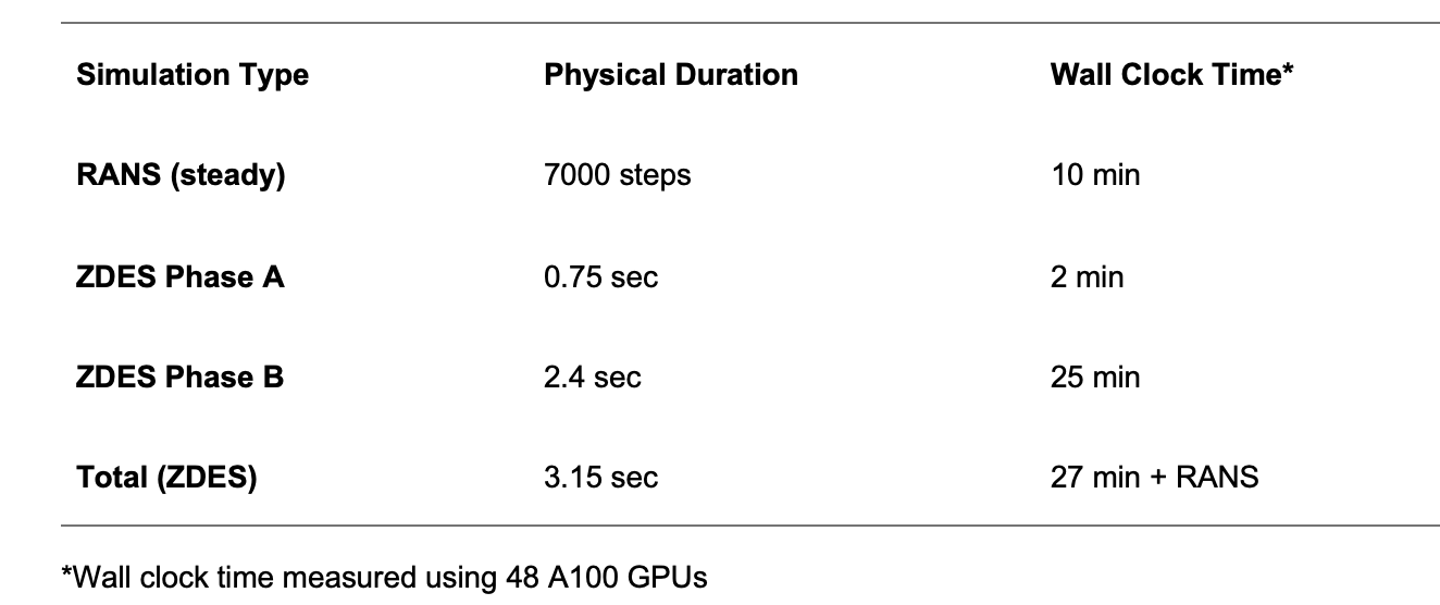
Table 1: Simulation Timing Summary | *Wall clock time measured using 48 A100 GPUs
This two-phase ZDES approach done automatically in sequence with adaptive time-stepping:
- A coarse time step (5e-3 s, CFL = 50 on a resolved mesh zone) to flush the RANS solution for 0.75 sec—completed in 2 minutes on 48 A200 GPUs
- A fine time step (1e-3 s, CFL = 10) for the main ZDES run, averaged over the last 2 seconds—completed in 25 minutes on 48 A100 GPUs
All of this, without sacrificing fidelity. Flow360’s ZDES results match physical testing within 1 drag count, capturing complex flow physics that engineers can trust.

Figure 8: Flow360 ZDES’s excellent prediction of delta forces prediction between two DrivAer configurations with the Test data
Right Answers for the Right Reasons
Physically accurate flow features are essential for design optimization. Many CFD tools struggle to resolve complex flow phenomena, particularly around critical regions like the A-pillar and side mirror, where flow separation and downstream vortices significantly impact the pressure distribution on the side window. Flow360’s ZDES results, however, show close agreement with test data, validating its ability to capture the true physics of the flow.
 |
 |
 |
This high level of accuracy continues along the symmetry plane of both the upper body and underbody, where Flow360’s pressure predictions align closely with wind tunnel data. Such consistency reinforces trust in the solver’s reliability for production use.
 |
 |
Even in the most challenging regions—such as the rear wake and underfloor—Flow360 delivers. The wake contours show excellent agreement with test results, clearly demonstrating that Flow360 captures not just trends, but the detailed unsteady structures that matter most to real-world aerodynamic performance.

Figure 5: Visualization of flow structure around A-piller and side mirror along with excellent agreement between Flow360 and Test data for pressure prediction on side mirror
Delta Prediction: Where It Counts in Design Optimization
In the production stage, the priority shifts from absolute accuracy to capturing aerodynamic deltas—the impact of design changes on performance. At this point, vehicle designs are largely frozen, and the focus shifts to fine-tuning specific components—such as mirrors, underbody panels, or wheel deflectors—to optimize efficiency. What matters most is the ability to reliably capture how each design tweak impacts overall drag performance.
One of AutoCFD4’s most important test cases was the front wheel arch deflector delta—a highly relevant real-world scenario given how often such features are refined late in the design cycle.

Figure 8: Flow360 ZDES’s excellent prediction of delta forces prediction between two DrivAer configurations with the Test data
Flow360 accurately captured both the magnitude and trend of the delta, enabling confident decision-making and reducing reliance on costly wind tunnel validation. It’s precisely why Flow360 is already trusted in production by leading automotive OEMs.
Real-World Validation: NIO Success Story
Flow360 isn’t just proven in benchmarks—it’s trusted in production. In collaboration with NIO Inc., we validated over 60 designs across SUVs and sedans. The results:
- Fastest Speed and Efficiency: Flow360’s simulation time is 10-100 times faster than traditional methods, completing complex simulations in just an hour on 8 L20 (10 mins on 8 H200)
- Unparalleled Accuracy: More than 94% of simulations show less than 3% deviation from physical wind tunnel tests, ensuring that design decisions are based on reliable data.
Many tools struggle in robustness and consistency across extensive test scenarios —Flow360 delivers.
In the example below Flow360 accurately captured the design delta Cd caused by a small change to air-intake. This was particularly challenging as it is located near the wheel well. With Flow360 you can have confidence in your results to make the right decisions.

Figure 9: Accurate prediction of delta Cd by Flow360 as compared to a competitor for a design change due to air-intake
And the Best Part? We’re Just Getting Started
Flow360 combines unmatched solver speed with high-fidelity results—redefining how automotive CFD gets done. But this is just the beginning.
Behind Flow360 is a world-class team shaping the future of simulation. We’re proud to be working with some of the most respected minds in the field—like Dr. Philippe Spalart, the pioneer behind the Spalart-Allmaras turbulence model; Dr. Mike Park, former NASA researcher and global leader in adaptive mesh refinement; and Dr. Roberto Della Ratta Rinaldi, former senior aerodynamicist at Aston Martin and McLaren, with over 15 years at the forefront of automotive aero analysis and methodology development.
Together, this team isn’t just evolving CFD—they’re accelerating it beyond anything the industry has seen. Flow360 enables interactive workflows at unprecedented speed, taking engineers from geometry to insight in hours, not days.
And there’s more ahead. In Q3 2025, we’ll be launching a major release focused on geometry, further simplifying simulation and introducing new levels of automation and intelligence into the workflow.
If you’re building the future, choose a partner that represents the future.
Experience Flow360—and see how fast innovation can move. Talk to an expert to learn more about Flow360.

Flexcompute announces PhotonForge, a groundbreaking photonic design automation platform that unifies the entire Photonic Integrated Circuit (PIC) development process into one seamless environment. With the rise of photonics as the solution to communication bottlenecks in modern data centers, PhotonForge offers an integrated solution to meet the industry’s most pressing challenges.
Computing power has skyrocketed by 60,000 times in recent years and input/output bandwidth and memory speeds have struggled to keep pace. This has created a performance gap that threatens to stall innovation in AI and large-scale computing. PhotonForge empowers designers to unlock the bandwidth and energy efficiency required for tomorrow’s most demanding applications, paving the way for scalable, efficient, and reliable photonic advancements.
Streamlined End-to-End Workflow for PIC Design
PhotonForge empowers photonic designers by integrating design, optimization, simulation, and fabrication-ready layouts into a seamless interface. With this innovative solution, designers can effortlessly create foundry-ready designs while maintaining the precision and flexibility required in today’s fast-evolving photonics landscape.
PhotonForge addresses a critical challenge in photonics: unifying diverse tools and workflows into a cohesive, end-to-end solution. By leveraging GPU-accelerated, multi-physics solvers and enabling compatibility with foundry Process Design Kits (PDKs), PhotonForge delivers:
- Layout editor
- Device-level simulation (optical, electrical)
- Compact model generation
- Circuit-level simulations
- Signal integrity analysis
This integrated approach reduces tape-out errors, shortens time-to-market, and lowers development costs to accelerate photonic innovation.
“PhotonForge is a groundbreaking solution that redefines photonic device design and automation,” Flexcompute President Vera Yang said. “We are empowering innovators to accelerate design, reduce time-to-market, and unlock new growth.”
Next-Level Performance with GPU-Accelerated Simulations
One of PhotonForge’s most powerful features is its GPU-accelerated multi-physics capabilities. Powered by Flexcompute’s cutting-edge solvers, including FDTD, MODE, RF, and CHARGE, PhotonForge enables simulations up to 500 times faster than traditional methods. This game-changing speed allows designers to explore more possibilities, optimize designs faster, and bring products to market with greater confidence and efficiency.
“The industry’s major players—TSMC, Broadcom, and Intel—are all doubling down on co-packaged optics to turbocharge I/O bandwidth,” said Prashanta Kharel, PhD, Technology Strategist at Flexcompute. “GPU-accelerated computing is the only way to tackle the complex, multi-dimensional problems standing in the way. It’s the future of photonics, and we’re making it happen.”
Pioneering the Future of Photonic Automation
PhotonForge is more than a tool—it’s a platform that empowers designers to push the boundaries of what’s possible in photonics. By combining advanced GPU-accelerated multi-physics simulation technology with an intuitive, unified workflow, it is redefining the future of photonic active device automation and enabling innovation at scale. Learn more.
SUBSCRIBE TO RECEIVE UPDATES
Stay up-to-date with the latest news and thought leadership in
multiphysics simulation technology.


 TERMS & CONDITIONS


 How the process works:
 Try this real URL to see an example: