


Tidy3D uses the Finite-Difference Time-Domain (FDTD) method, which is a popular technique for rigorously solving Maxwell's equations. However, like all numerical methods, it can sometimes diverge if not properly set up. An FDTD simulation can diverge due to various reasons. In this article, we discuss common FDTD setting issues that could potentially lead to simulation divergence. If your simulation diverged, please follow this article and perform thorough troubleshooting, which will likely resolve the issue and ensure that your next FDTD run is stable.
Structures Inserted into PML at an Angle
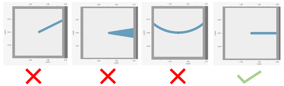
Perfectly matched layer (PML) is the most commonly used boundary condition in FDTD simulations to truncate a simulation domain and absorb outgoing radiation. However, many divergence issues are associated with the use of PML. One of the most common causes is a structure that intersects the PML in a way that is not translationally invariant in the direction normal to the boundary. This is particularly common in simulations with photonic waveguides, where PML intersects a waveguide bend, a waveguide taper, or a ring resonator. In the sketch below, the first three geometries are not translationally invariant into the PML, while the fourth geometry is invariant because the straight waveguide enters the PML normally.
Starting from version 2.11, Tidy3D's PML boundary has extrude_structures=True by default. With this setting, structures that touch a PML boundary are automatically extruded through the PML so that the geometry seen by the PML is translationally invariant. This makes simulations much less likely to diverge than they would be with extrude_structures=False, where the original geometry remains in the PML. Therefore, with respect to divergence this precaution is mostly relevant if extrude_structures=False has been set, although in some cases even the default setting True can lead to divergence due to evanescent fields at the kink shown below.
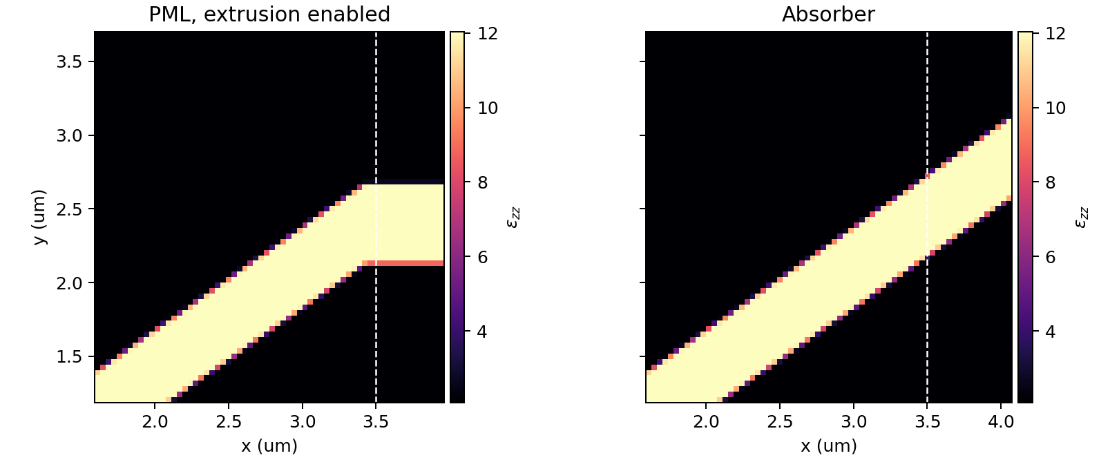
This automatic extrusion is a stability safeguard, but it is still a geometry modification. If the original structure was not translationally invariant into the PML, the extruded geometry can contain an artificial kink or termination, and that can create spurious reflections. When the solver detects that extrusion has overwritten original translational variance, it emits a warning in the solver log. The figure below shows a 35 degree waveguide crossing the positive x boundary. A permittivity monitor near the boundary shows that the default PML case is extruded into the PML, while the absorber case preserves the slanted geometry.
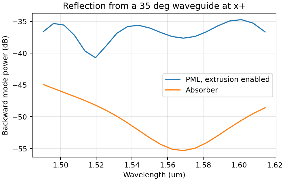
The reflection spectrum illustrates the same tradeoff. For a straight waveguide in an infinite domain, the expected backward wave is zero. In this finite simulation, a small backward component remains even with the absorber because oblique mode injection and the finite grid are not perfectly ideal. The extruded PML case, however, has a much larger backward mode power because the artificial boundary kink reflects part of the guided mode. In this example, the peak reflected power is about 10 dB higher with the default extruded PML than with the absorber.
Therefore, if a structure is not translationally invariant into a PML and the simulation diverges, switching extrude_structures=False back to the default True may restore stability, but it should not be treated as a guarantee that the result is physically clean. Inspect the solver log, look for unexpected reflections, and consider replacing that boundary with an Absorber when preserving the geometry is more important than the ideal low reflection of a well-matched PML.
Dispersive Material into PML
Incorporating a dispersive material into PML can also cause simulation divergence in certain scenarios. If your simulation lacks any structures inserted into PML at an angle but includes dispersive material in PML, it is advisable to substitute nondispersive material for the dispersive material. Alternatively, if dispersion is necessary, switching PML to absorber can effectively address the issue.
Evanescent Field Leaks into PML
PML can effectively absorb outgoing radiation with minimum reflection as if the radiation just propagates into the free space. However, it's important to keep in mind that PML only absorbs propagating fields. For evanescent fields, PML can act as an amplification medium and cause a simulation to diverge. In Tidy3D, a warning will appear if the distance between a structure is smaller than half of a wavelength to prevent evanescent fields from leaking into PML. In most cases, the evanescent field will naturally die off within half a wavelength, but in some instances, a larger distance may be required. One example is when using periodic or Bloch boundary conditions in two dimensions and PML in the last dimension only. In such simulations, there could be quasi-guided modes in the periodic directions which have very long evanescent tails in the PML direction. If a simulation diverges and you suspect that evanescent fields may be leaking into PML, simply increase the simulation domain size to avoid this issue.
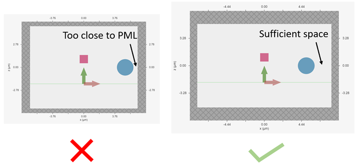
Additionally, sources like PointDipole, UniformCurrentSource, or CustomFieldSource can inject evanescent fields, so it's important to leave enough space between them and PML.
Gain Medium from Fitting
When defining a dispersive material using an external fitter or Tidy3D's regular fitter, it is crucial to ensure that the fit is passive. Although the material may appear passive within the simulation frequency range, the fitting process could result in a gain medium outside of the frequency range, leading to simulation divergence. To avoid this, Tidy3D offers a FastDispersionFitter that enforces passive fitting across all frequencies. It is highly recommended to use this fitter for dispersive medium fitting.
Courant Factor is Too Large
When conducting FDTD simulations, it's important to satisfy the Courant factor condition. This condition, also known as the Courant number or Courant-Friedrichs-Lewy (CFL) condition, is a numerical requirement that relates the time step (Δt) to the spatial step (Δx), and sometimes to the wave propagation speed (c) in the system. The Courant factor can be determined by the formula: C = c * Δt / Δx. To ensure the stability of the numerical solution, the Courant factor must be equal to or less than 1, according to the CFL condition: C ≤ 1. By satisfying this condition, the simulation can accurately capture the wave propagation in the system, as information cannot travel further than one spatial step in one time step. Violating the CFL condition can cause the simulation to diverge and become unstable. Therefore, it's crucial to choose appropriate time and spatial step sizes for any FDTD simulation.
Tidy3D uses a default Courant factor of 0.99. When a dispersive material with eps_inf < 1 is used, the Courant factor will be automatically adjusted to be smaller than sqrt(eps_inf)to ensure stability. If your simulation still diverges despite addressing any other issues discussed above, reducing the Courant factor may help.
Additional Notes on Absorber
As discussed above, using absorber boundary is often a good remedy to resolve divergence issues related to PML. The adiabatic absorber is a multilayer system with gradually increasing conductivity. As briefly discussed above, the absorber usually has a larger undesired reflection compared to PML. In practice, this small difference rarely matters, but is important to understand for simulations that require high accuracy. There are two possible sources for the reflection from absorbers. The first, and more common one, is that the ramping up of the conductivity is not sufficiently slow, which can be remedied by increasing the number of absorber layers (40 by default). The second one is that the absorption is not high enough, such that the light reaches the PEC boundary at the end of the Absorber, travels back through it, and is still not fully attenuated before re-entering the simulation region. If this is the case, increasing the maximum conductivity (see the API reference) can help. In both cases, changing the order of the scaling of the conductivity (sigma_order) can also have an effect, but this is a more advanced setting that we typically do not recommend modifying.
Contact Tidy3D Support
If the solutions provided in this article did not resolve your simulation issues, please contact Tidy3D Support. Our experienced support engineers will assist you in resolving the problems with your simulation settings.

