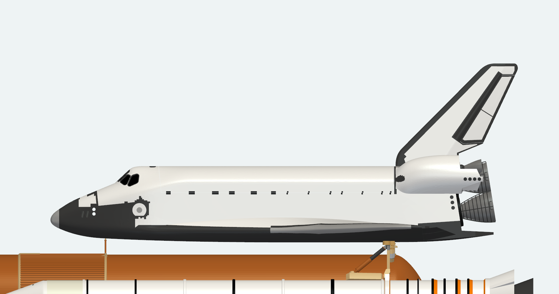
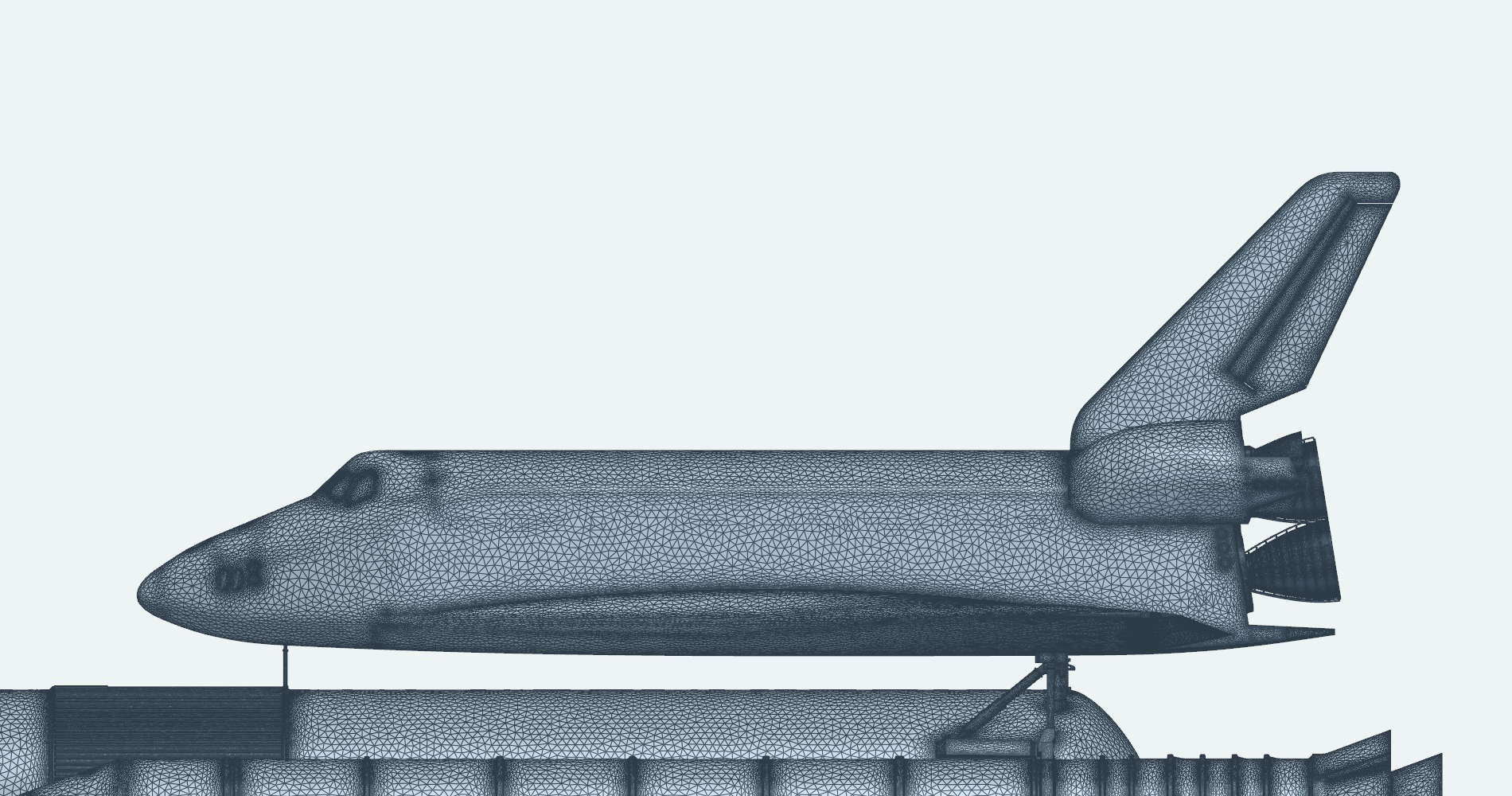
The Space Shuttle. Orbiter, external tank and solid rocket boosters
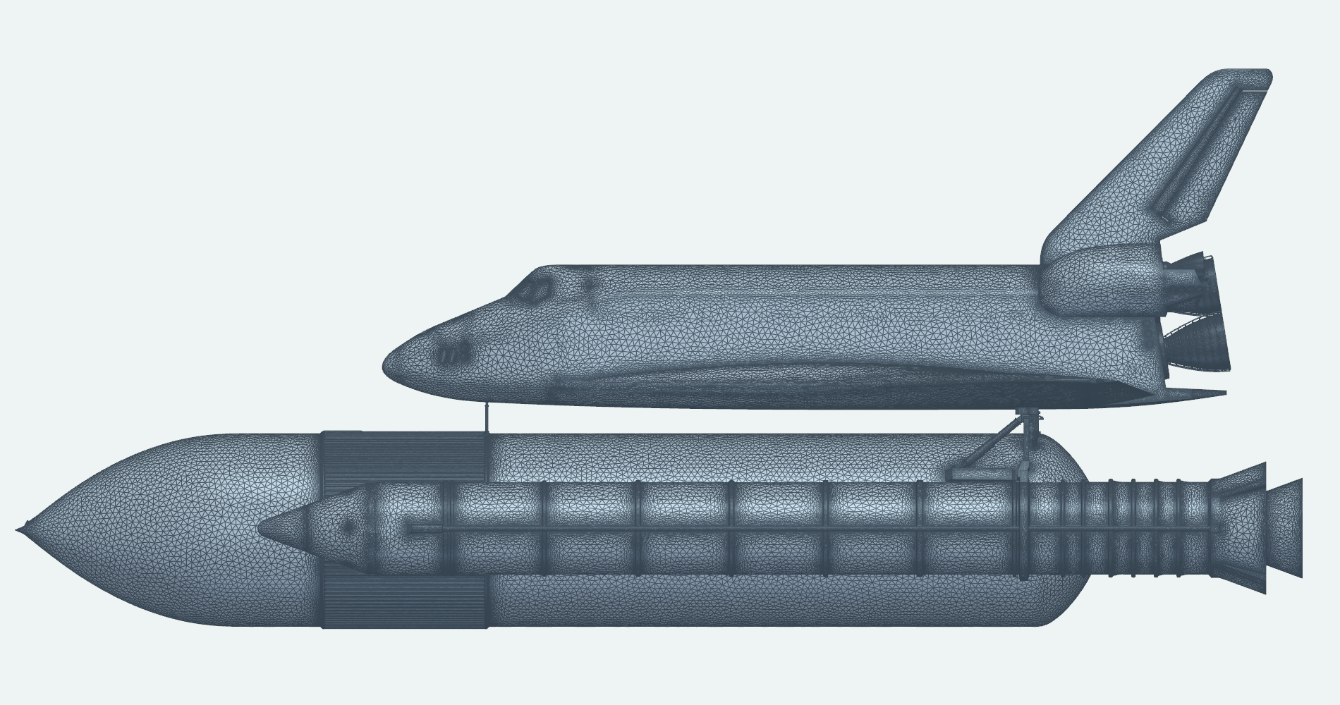
The Space Shuttle launch stack tests GeometryAI’s ability to mesh large assemblies that combine expansive surfaces, thin components and small details, a recurring challenge in industrial applications. The winged orbiter, the external tank and the two solid rocket boosters are joined by attachment struts and fittings, and the model spans length scales from the full-length tank and boosters down to the stiffening rings on the main-engine nozzles and the reaction control thrusters on the orbital maneuvering system (OMS) pods. GeometryAI turns the complete assembly into a single simulation-ready surface mesh, closing gaps between panels and resolving intersections between bodies while preserving small attachment and propulsion details alongside the large smooth surfaces.
From CAD Assembly to Surface Mesh
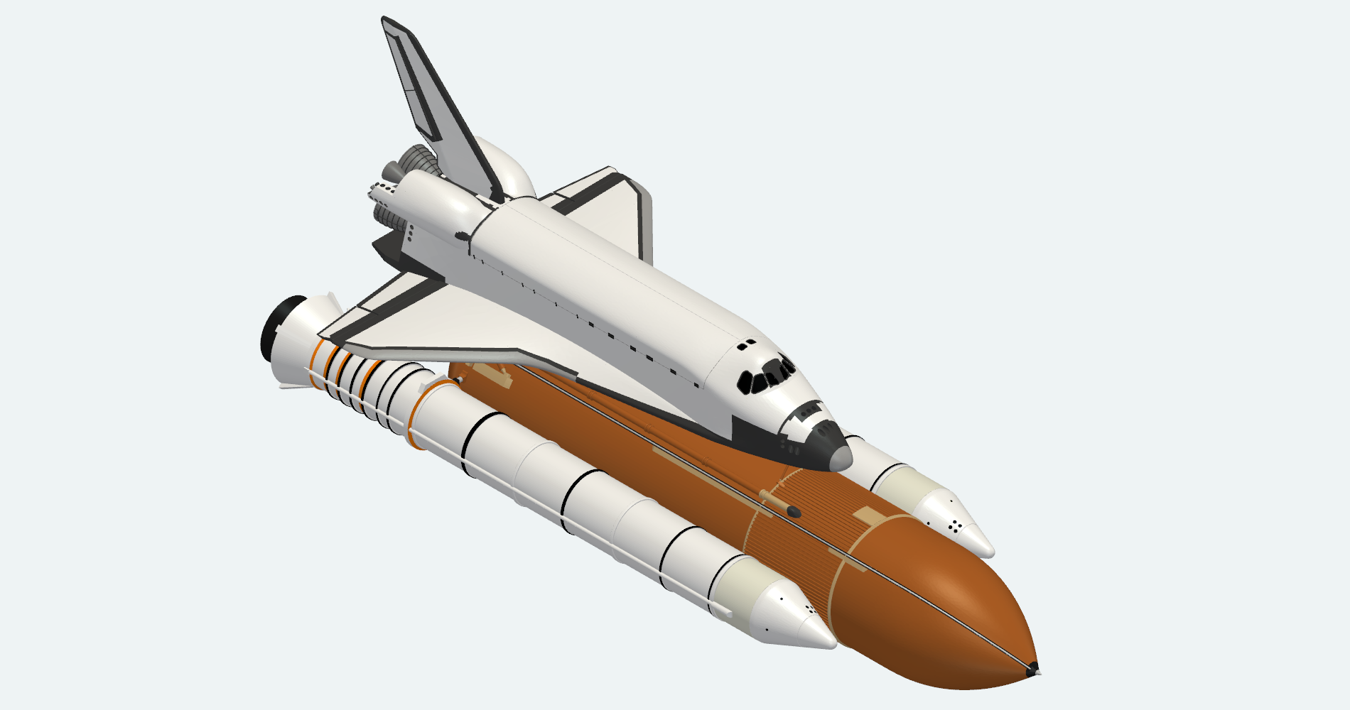
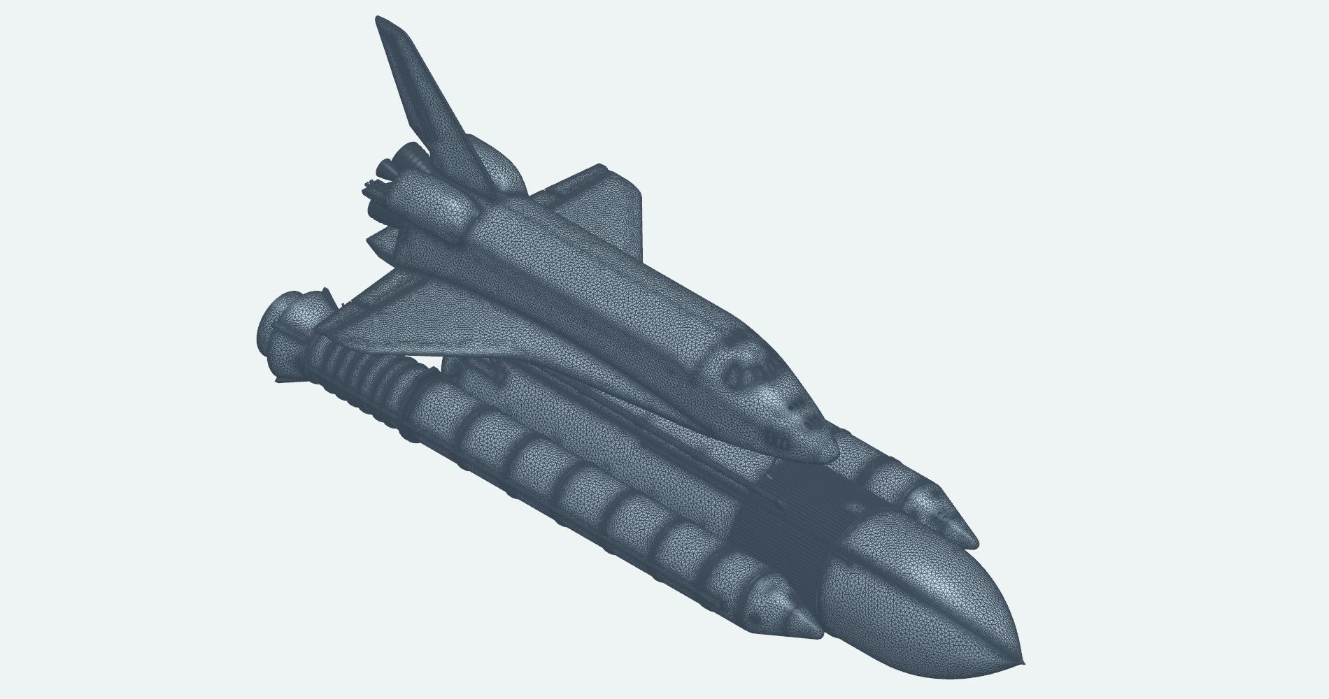
This section gives an overview of the complete model, comparing the GeometryAI surface mesh side by side with the original geometry.
Three-quarter view
The mesh covers the whole stack, from the orbiter's wings and vertical tail to the external tank and both boosters.
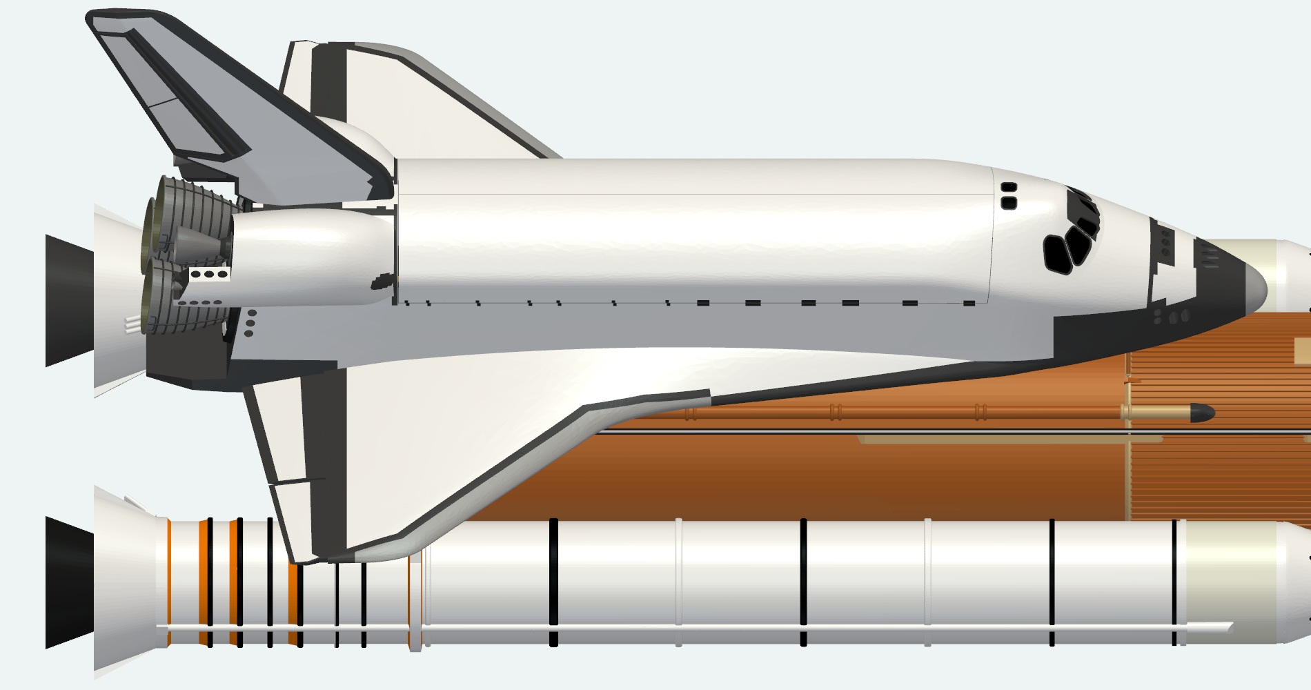
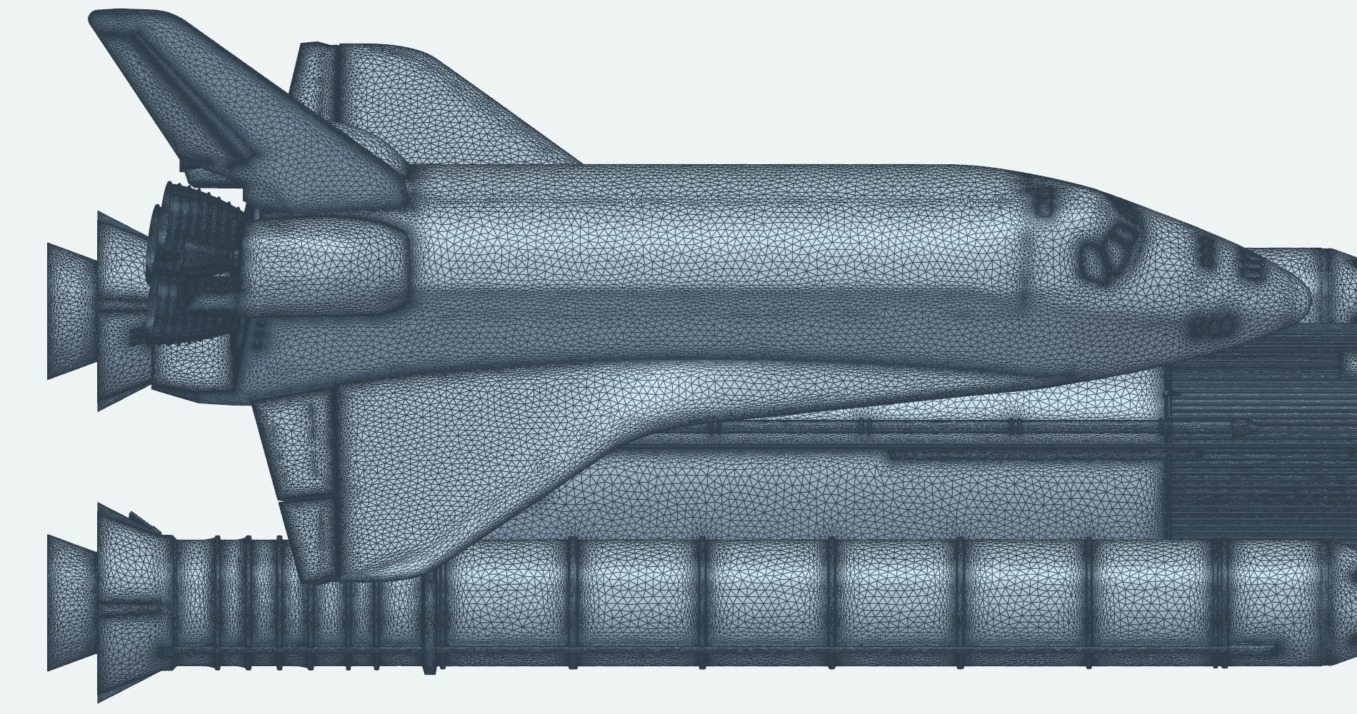
Orbiter from above
From above, the payload bay doors, the wings and the OMS pods lie over the external tank and the booster beneath them.
Main Engines and OMS Pods
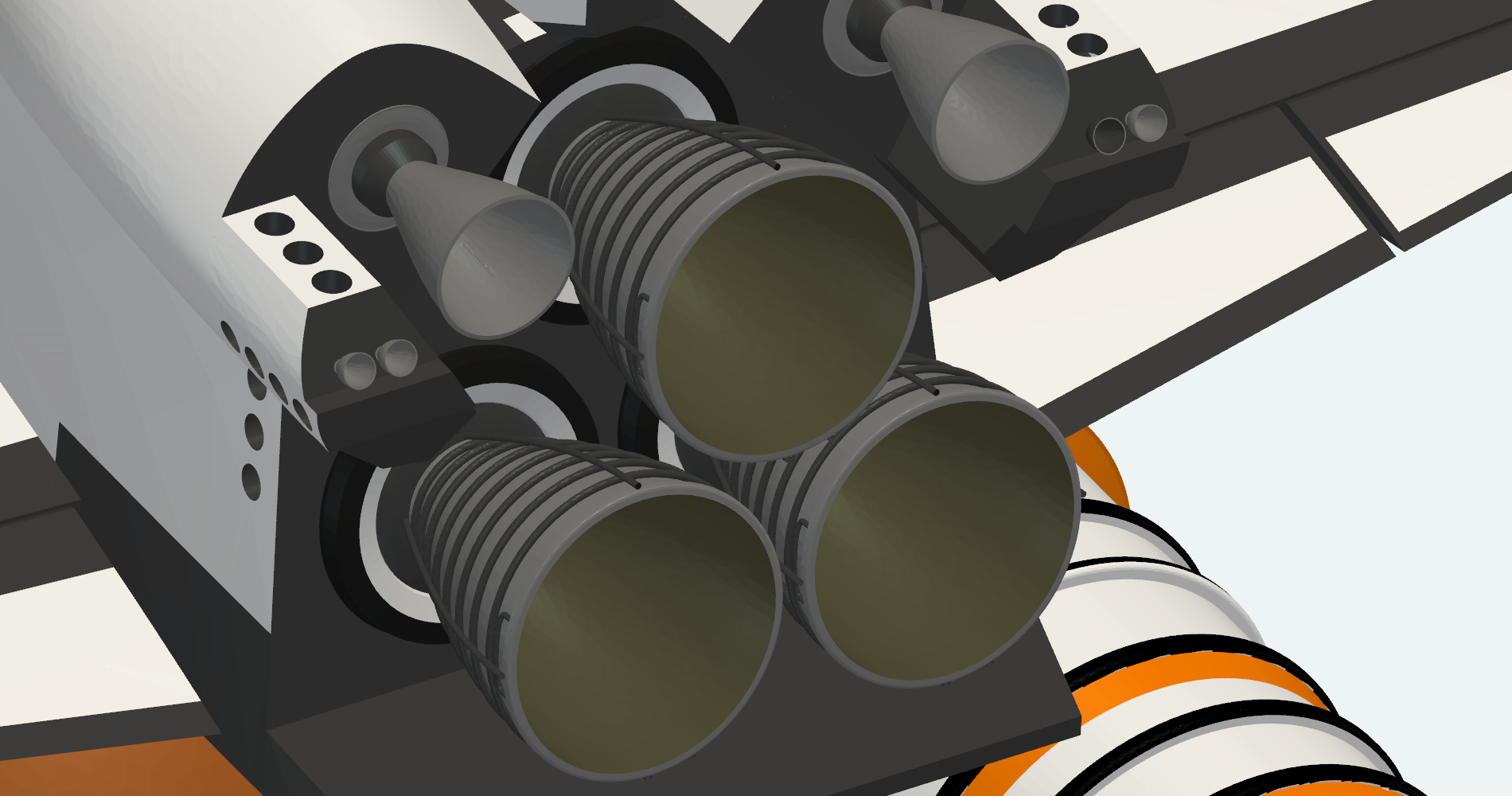
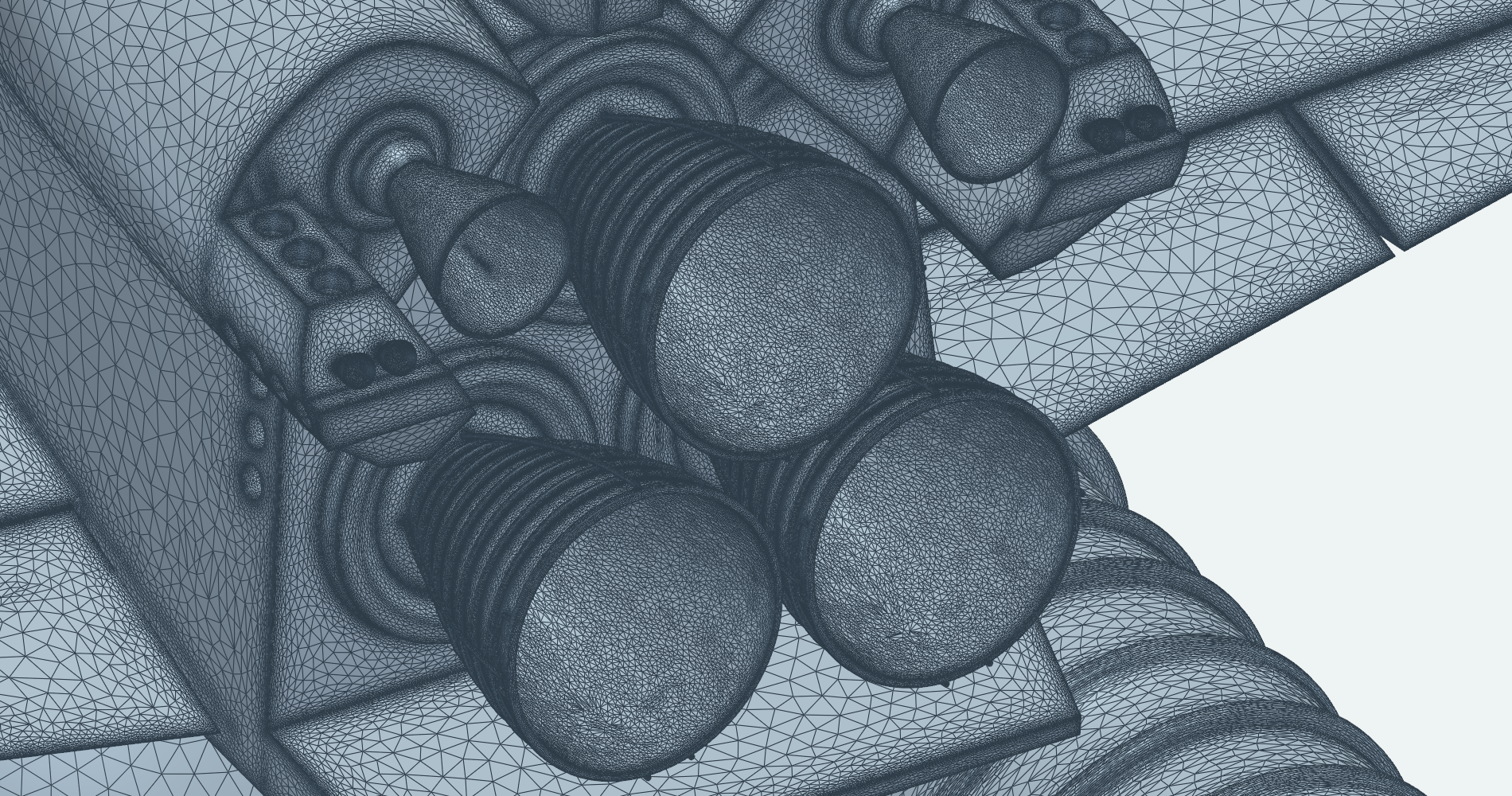
The orbiter's aft fuselage packs the three main engines, the two orbital maneuvering system (OMS) engines and the aft reaction control system (RCS) thrusters close together. A geometry refinement applied to a box around the engines tightens the geometry accuracy there, so the mesh is finer around these parts and stays coarse on the neighboring smooth surfaces.
Engine cluster
The three main engines and the two OMS engines, with a solid rocket booster below.
Nozzle stiffening rings
The stiffening rings wrapped around each main-engine nozzle are thin, closely spaced features, and the mesh resolves each ring individually.
Nozzle exits and RCS thrusters
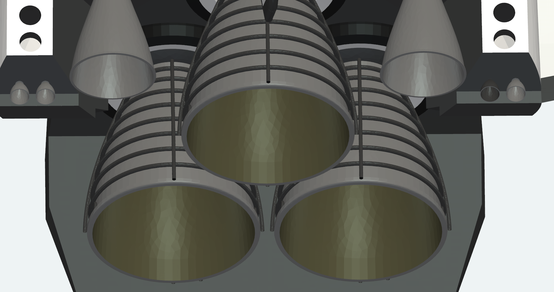
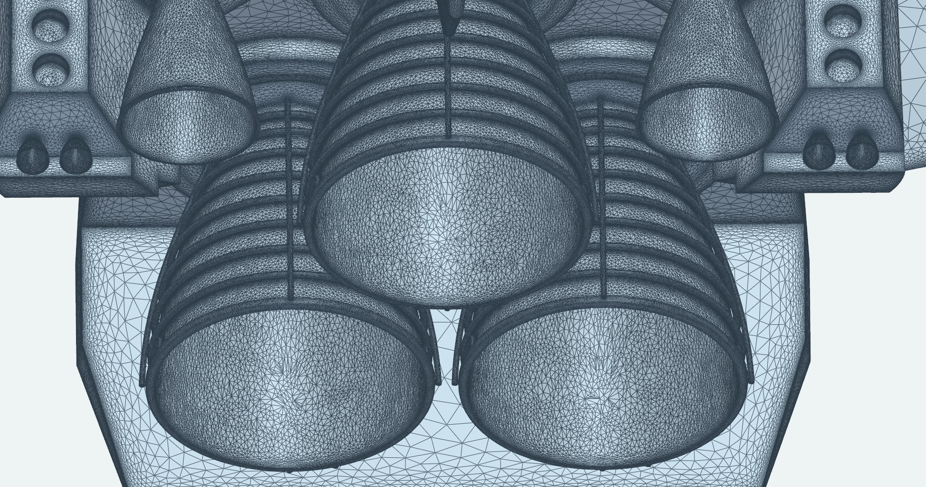
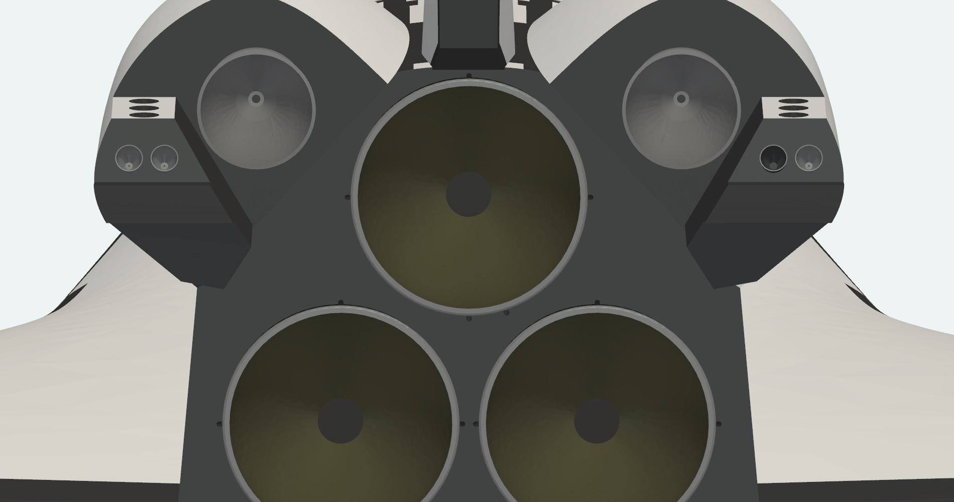
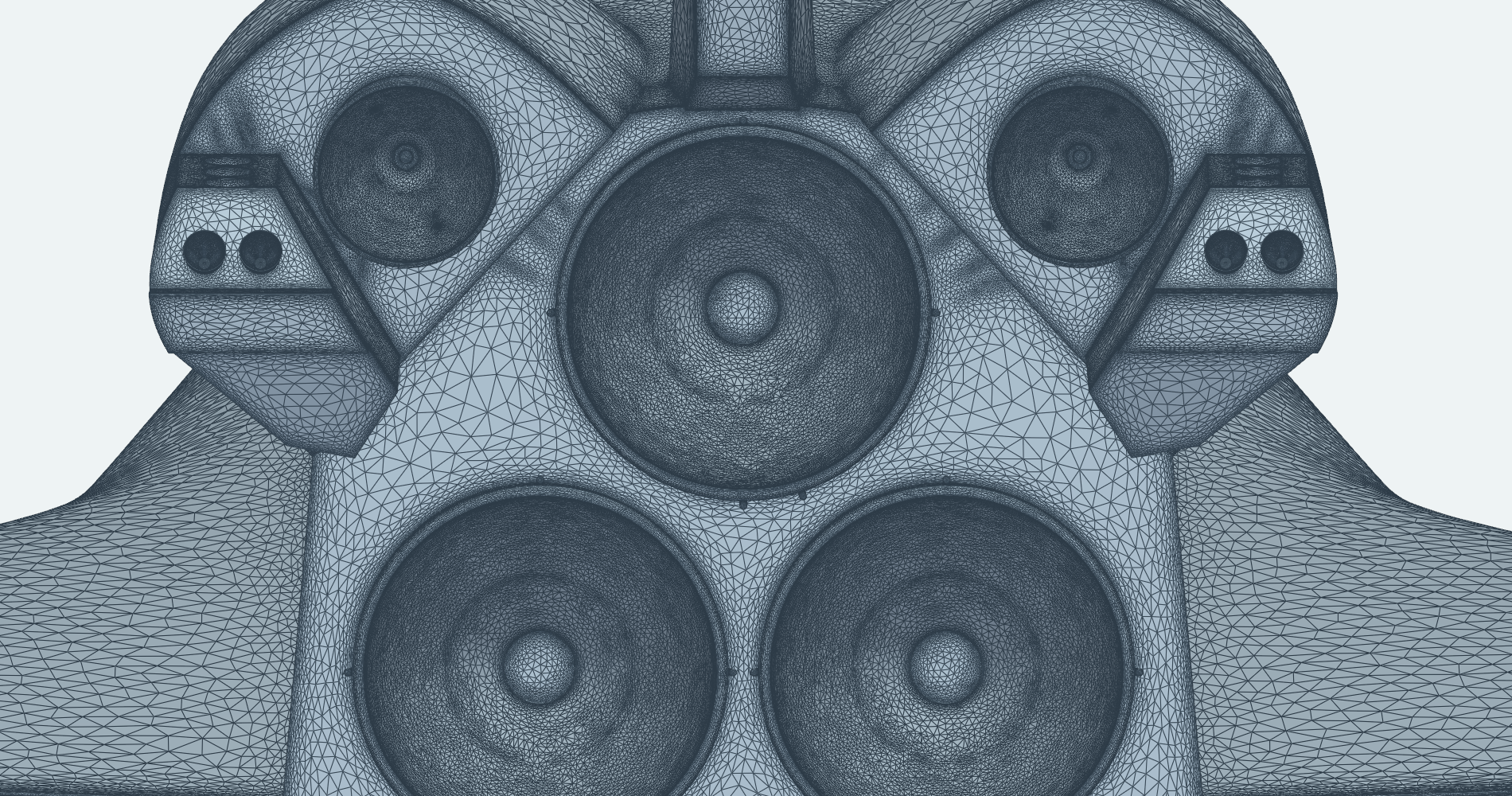
Seen from behind, the mesh follows each nozzle exit lip and the small RCS thruster ports on both OMS pods.
Bipod, Feedline, Boosters and Elevons
The most slender parts of the stack are the attachment hardware between the vehicles, the stiffening rings and cable tunnel running along the boosters, and the trailing edges of the orbiter's control surfaces. A second geometry refinement tightens the geometry accuracy on the elevon trailing-edge bodies.
Forward attachment
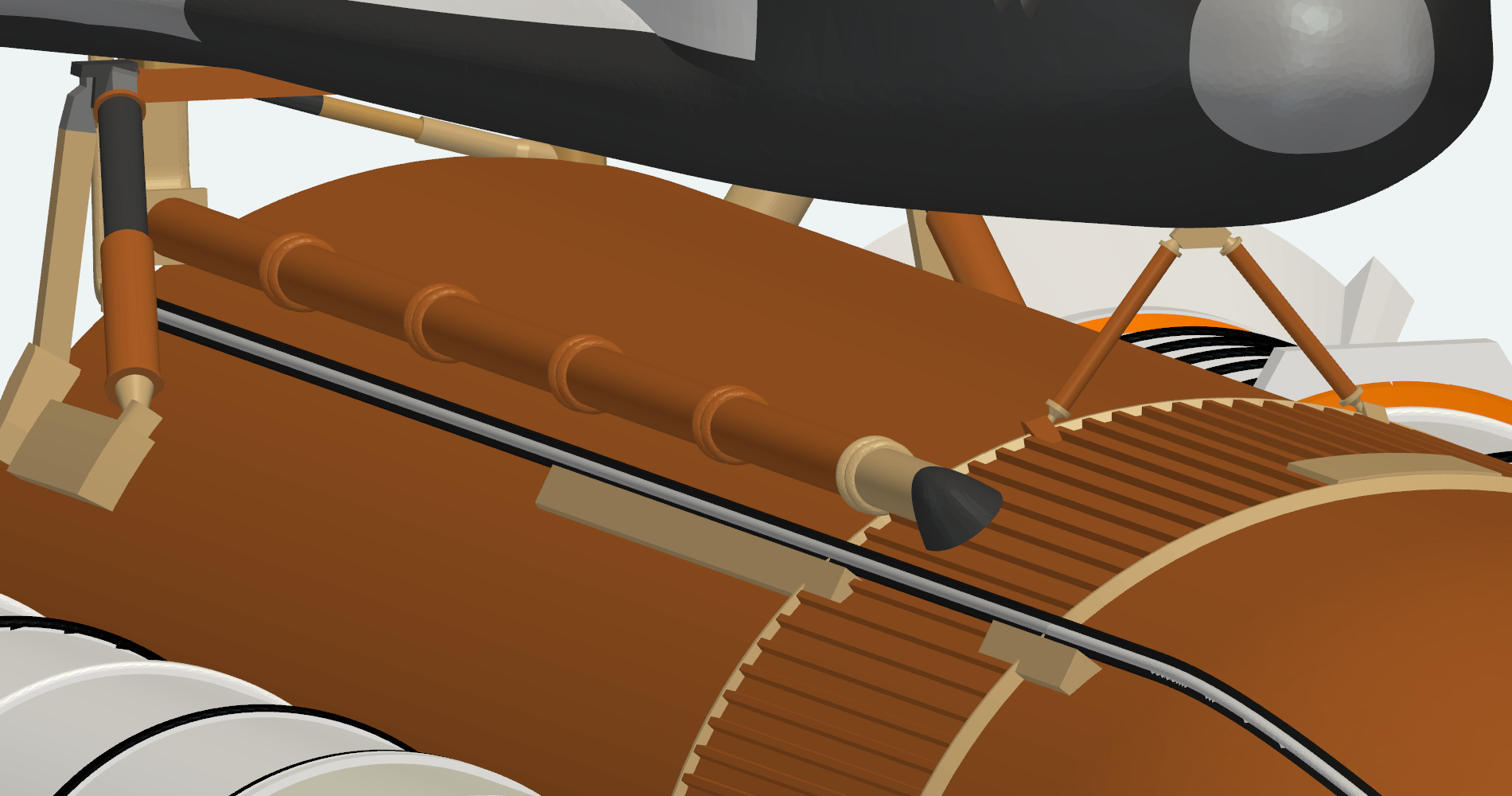
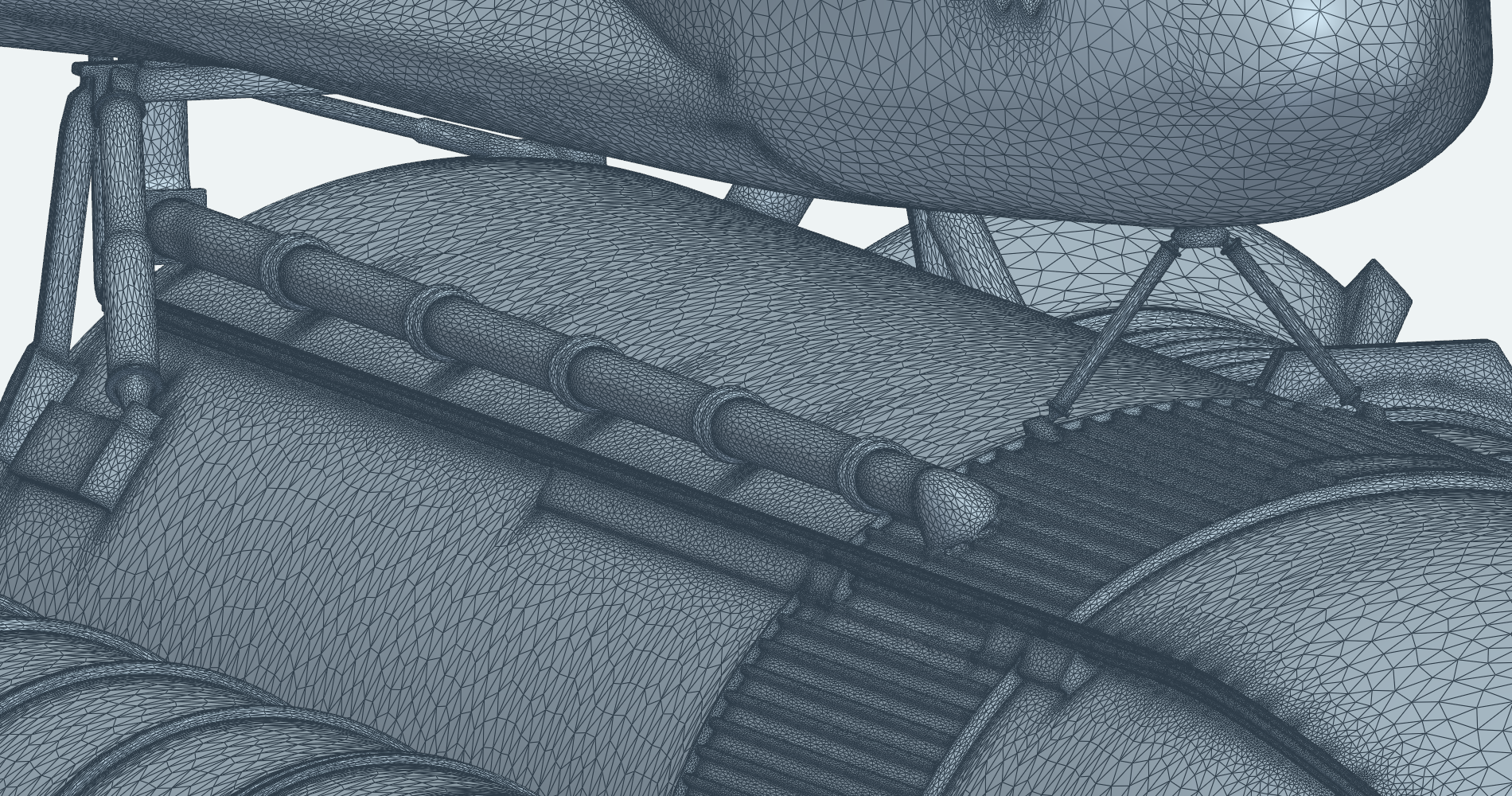
The forward bipod, the feedline with its support brackets and the stringer-stiffened intertank all appear in the mesh.
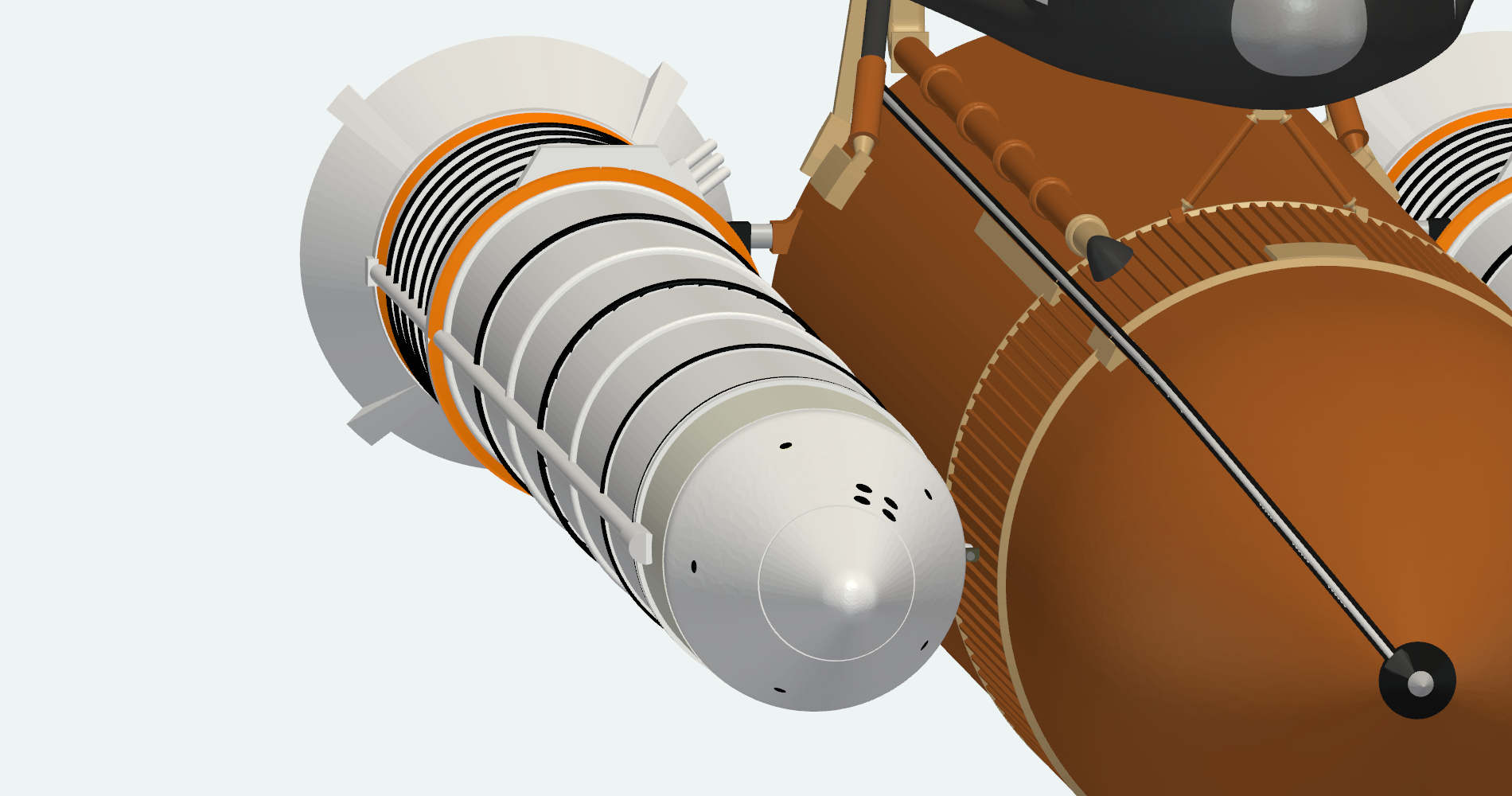
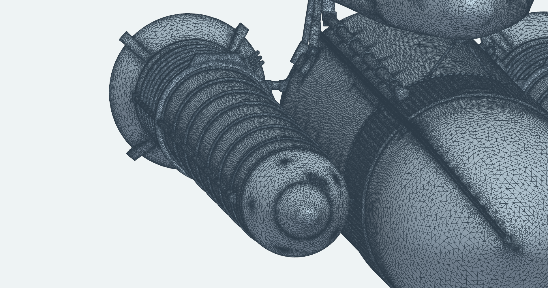
Solid rocket booster
Looking aft along a booster, the mesh follows the nose cap, the closely spaced stiffening rings, the cable tunnel and the strut that ties the booster to the external tank.
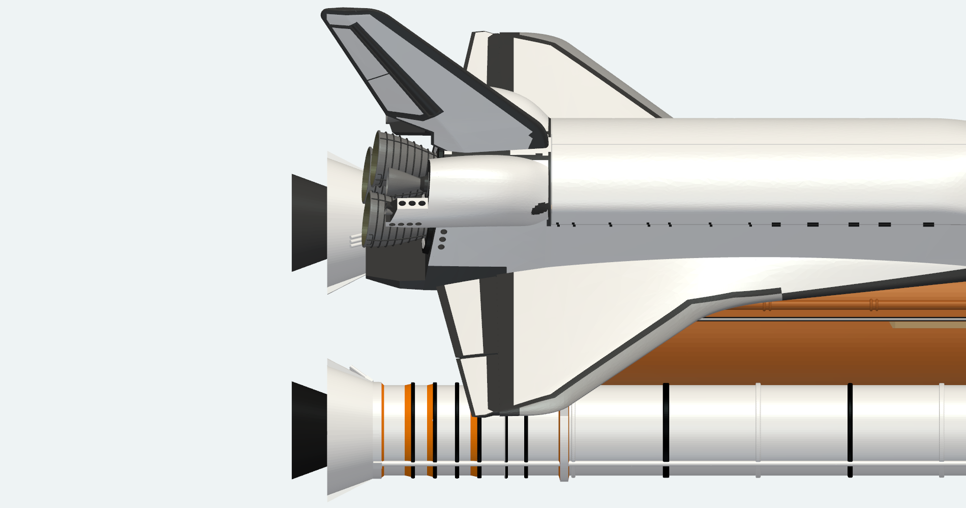
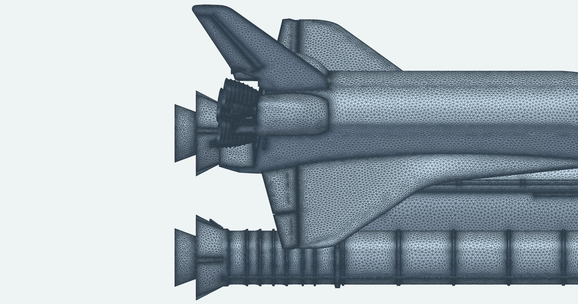
Tail and elevons
Viewed from above, the elevons along the wing trailing edges, the vertical tail and the booster nozzles appear together.
Complete Mesh
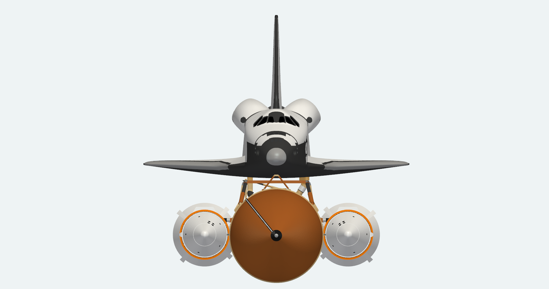
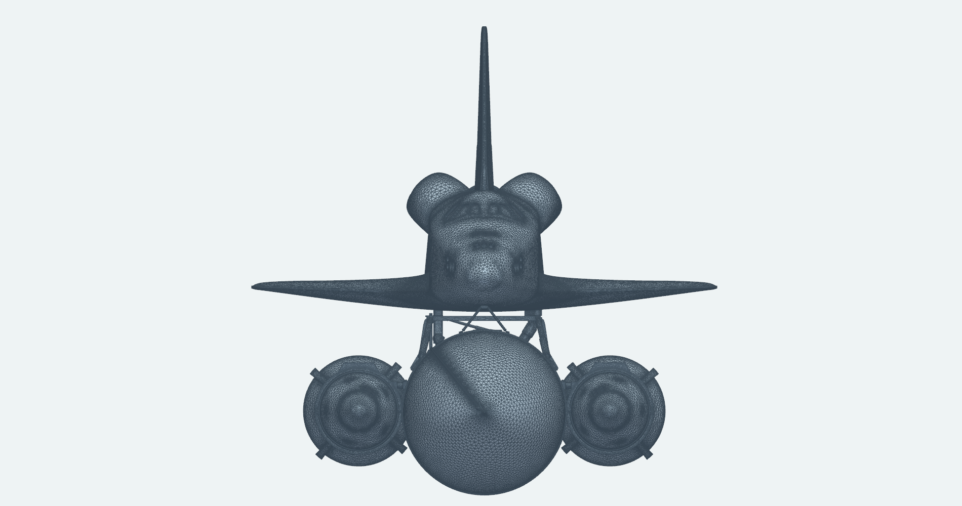
Two more views of the finished mesh: the whole stack head-on, and the orbiter from the side above the external tank, both part of a single simulation-ready surface.
Front view
Head-on, the orbiter sits on the forward bipod above the external tank, with a solid rocket booster on each side.
Orbiter side
Side-on, the forward bipod and the aft attachment hardware span the gap between the orbiter and the external tank.