





Author: Tianle Xu, Rensselaer Polytechnic Institute
This notebook uses the reflector from solid_xy_xz.stl to generate an initial 40-slice cubic Bezier parameterization. This is parametric adjoint shape optimization, not 3D topology optimization.
Parameter vector:
- 40 reflector slices.
- Each slice has 4 cubic Bezier control points
P0, P1, P2, P3in the(x, z)cross-section. -
P0andP3are fixed to preserve the fitted reflector endpoints and overall reflector dimension. - Only the handle points
P1andP2are optimized. - Each optimized handle contributes two variables:
xandz.
Therefore:
len(p) = 40 slices * 2 handle points/slice * 2 coordinates/point = 160
The slice y positions are fixed from the STL fit. Bounds are applied directly to the P1 and P2 handle coordinates so the optimizer cannot move the reflector too far from the fitted starting shape.
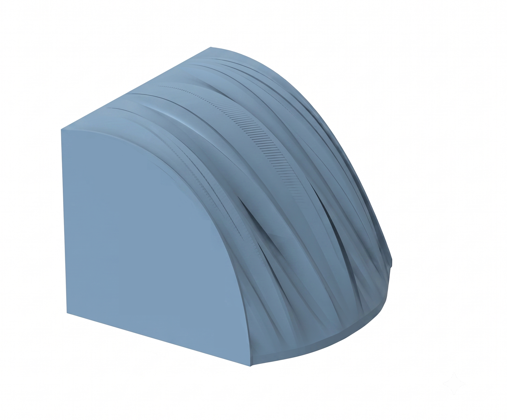
Imports
from __future__ import annotations

import math
from pathlib import Path

import autograd.numpy as anp
import matplotlib.pyplot as plt
import numpy as np
import tidy3d as td
import tidy3d.web as web
import trimesh
import xarray as xr
from autograd import value_and_grad
from tidy3d.plugins.mode import ModeSolver
from tidy3d.plugins.mode.web import run as run_mode_solver

print(f"Tidy3D version: {td.__version__}")
plt.rcParams.update({"figure.figsize": (9, 5), "axes.grid": True, "grid.alpha": 0.25})
Tidy3D version: 2.11.2
User Settings
All geometric units in Tidy3D are micrometers.
STL_PATH = Path("./misc/solid_xy_xz.stl")
RESULTS_DIR = Path("results")
RESULTS_DIR.mkdir(exist_ok=True)

# Bezier slice model.
NUM_SLICES = 40
BEZIER_DEGREE = 3
NUM_PROFILE_POINTS = 120
NUM_POLYGON_POINTS = 40

# Cross-slice smoothing. This smooths the fitted Bezier control-point trajectories along y.
SMOOTH_CONTROL_POINTS_ACROSS_Y = False
SMOOTH_ENDPOINT_LAMBDA = 1.0
SMOOTH_HANDLE_LAMBDA = 8.0
SMOOTH_FIX_FIRST_LAST_SLICE = True

# Bounds: keep the optimized Bezier handles close to the fitted starting shape.
# P0 and P3 are fixed, so only P1/P2 are bounded and optimized.
HANDLE_DX_BOUND_UM = 2
HANDLE_DZ_BOUND_UM = 2

# Geometry placement.
STL_Z_SHIFT_UM = -2.0

# Source: 480 nm square SiN waveguide tip launching horizontally from the reflector left side.
TIP_SIZE_UM = 0.480
TIP_LENGTH_UM = 4.0
TIP_CLADDING_SIZE_UM = 2.0
MODE_SOURCE_SIZE_Y_UM = 3.0
MODE_SOURCE_SIZE_Z_UM = 3.0
WAVEGUIDE_Z_UM = 0.0
# Keep the mode-source plane inside the cladded tip by several grid cells.
# A 50 nm gap was too close to the tip end and triggered a mode-solver boundary warning.
TIP_SOURCE_GAP_FROM_REFLECTOR_UM = 0.30
SOURCE_DIRECTION = "+"

# ARROW output monitor: xy plane normal to z, placed just below the reflector bottom.
ARROW_CENTER_X_UM = 9.0
ARROW_MONITOR_GAP_UM = 0.05

# ARROW waveguide geometry: round, concentric anti-resonant layers, propagating along z.
# Air core, then SiO2 / SiN / SiO2 anti-resonant layers, surrounded by Si.
ARROW_CORE_RADIUS_UM = 7.0
ARROW_LAYER_SIO2_1_THICKNESS_UM = 0.472
ARROW_LAYER_SIN_THICKNESS_UM = 0.17724
ARROW_LAYER_SIO2_2_THICKNESS_UM = 0.28
ARROW_WAVELENGTH_UM = 1.31

# ARROW mode solver settings.
ARROW_NUM_MODES = 4
ARROW_TARGET_NEFF = 0.996
ARROW_MODE_NUM_PML = (20, 20)
ARROW_MODE_BUFFER_UM = 3.0 * ARROW_WAVELENGTH_UM
ARROW_MODE_SOLVER_PATH = RESULTS_DIR / "arrow_mode_solver.hdf5"
RECOMPUTE_ARROW_MODE = False

# Materials. Replace these if the reflector/tip material stack is different.
n_air = 1.00
n_sio2 = 1.444
n_reflector = 1.60
n_tip = 2.00
n_sin = 2.00
n_si = 3.48
background_medium = td.Medium(permittivity=n_air**2)
sio2_medium = td.Medium(permittivity=n_sio2**2)
reflector_medium = td.Medium(permittivity=n_reflector**2)
tip_medium = td.Medium(permittivity=n_tip**2)
sin_medium = td.Medium(permittivity=n_sin**2)
si_medium = td.Medium(permittivity=n_si**2)

# Simulation controls. Keep coarse until geometry is approved.
min_steps_per_wvl = 15
pml_buffer_um = 1.2
run_time_factor = 60
E_FIELD_COMPONENTS = ("Ex", "Ey", "Ez")
FOM_MONITOR_NAME = "arrow_match"
OPT_FIELDS_MONITOR_NAME = "opt_fields"
OPT_FIELDS_BUFFER_UM = 0.35
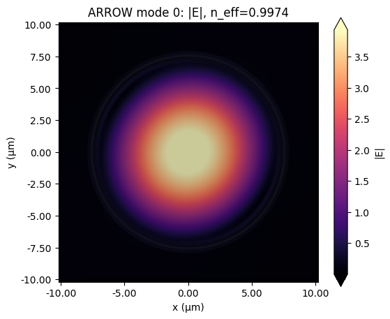
Solve the ARROW Waveguide Mode in Tidy3D
Instead of parsing an external ARROW mode-profile file, this section builds the round ARROW waveguide cross-section directly in Tidy3D and solves for its guided mode with the ModeSolver plugin. The waveguide propagates along z, with a concentric-layer cross-section in x-y:
- Air core, radius
ARROW_CORE_RADIUS_UM = 7.0 um - SiO2 layer, thickness
0.472 um - SiN layer, thickness
0.17724 um - SiO2 layer, thickness
0.28 um - Surrounded by Si
The mode solver searches for the ARROW_NUM_MODES modes closest to ARROW_TARGET_NEFF = 0.996, and the mode whose effective index is nearest that target is selected as the ARROW mode. The solve runs on the server (subpixel-accurate) and the resulting ModeSolverData is cached to ARROW_MODE_SOLVER_PATH; if that file already exists, it is reloaded from disk instead of resubmitting the mode-solver job, so this only needs to run once. Set RECOMPUTE_ARROW_MODE = True to force a fresh solve.
arrow_r_core_um = ARROW_CORE_RADIUS_UM
arrow_r_sio2_1_um = arrow_r_core_um + ARROW_LAYER_SIO2_1_THICKNESS_UM
arrow_r_sin_um = arrow_r_sio2_1_um + ARROW_LAYER_SIN_THICKNESS_UM
arrow_r_sio2_2_um = arrow_r_sin_um + ARROW_LAYER_SIO2_2_THICKNESS_UM

# Concentric layers, largest radius first: later structures override earlier ones where they overlap.
arrow_outer_sio2 = td.Structure(
    geometry=td.Cylinder(center=(0, 0, 0), axis=2, radius=arrow_r_sio2_2_um, length=td.inf),
    medium=sio2_medium,
    name="arrow_outer_sio2",
)
arrow_sin_layer = td.Structure(
    geometry=td.Cylinder(center=(0, 0, 0), axis=2, radius=arrow_r_sin_um, length=td.inf),
    medium=sin_medium,
    name="arrow_sin_layer",
)
arrow_inner_sio2 = td.Structure(
    geometry=td.Cylinder(center=(0, 0, 0), axis=2, radius=arrow_r_sio2_1_um, length=td.inf),
    medium=sio2_medium,
    name="arrow_inner_sio2",
)
arrow_air_core = td.Structure(
    geometry=td.Cylinder(center=(0, 0, 0), axis=2, radius=arrow_r_core_um, length=td.inf),
    medium=background_medium,
    name="arrow_air_core",
)

arrow_mode_extent_um = 2 * arrow_r_sio2_2_um + ARROW_MODE_BUFFER_UM
arrow_mode_sim = td.Simulation(
    center=(0, 0, 0),
    size=(arrow_mode_extent_um, arrow_mode_extent_um, 1.0),
    medium=si_medium,
    structures=[arrow_outer_sio2, arrow_sin_layer, arrow_inner_sio2, arrow_air_core],
    run_time=1e-12,
    grid_spec=td.GridSpec.auto(wavelength=ARROW_WAVELENGTH_UM, min_steps_per_wvl=min_steps_per_wvl),
    boundary_spec=td.BoundarySpec.all_sides(boundary=td.PML()),
)

lambda0_um = ARROW_WAVELENGTH_UM
freq0 = td.C_0 / lambda0_um
freqw = 0.1 * freq0

arrow_mode_plane = td.Box(center=(0, 0, 0), size=(td.inf, td.inf, 0))
arrow_mode_spec = td.ModeSpec(
    num_modes=ARROW_NUM_MODES,
    target_neff=ARROW_TARGET_NEFF,
    precision="double",
    num_pml=ARROW_MODE_NUM_PML,
)
arrow_mode_solver = ModeSolver(
    simulation=arrow_mode_sim,
    plane=arrow_mode_plane,
    mode_spec=arrow_mode_spec,
    freqs=[freq0],
)

if ARROW_MODE_SOLVER_PATH.exists() and not RECOMPUTE_ARROW_MODE:
    arrow_mode_data = td.ModeSolverData.from_file(str(ARROW_MODE_SOLVER_PATH))
    print(f"Loaded cached ARROW mode solver data from {ARROW_MODE_SOLVER_PATH}")
else:
    arrow_mode_data = run_mode_solver(arrow_mode_solver, task_name="arrow_waveguide_mode_solver", verbose=True)
    arrow_mode_data.to_file(str(ARROW_MODE_SOLVER_PATH))
    print(f"Saved ARROW mode solver data to {ARROW_MODE_SOLVER_PATH}")

arrow_n_complex = np.asarray(
    arrow_mode_data.n_complex.sel(f=freq0, method="nearest").values, dtype=complex
).reshape(-1)
ARROW_MODE_INDEX = int(np.argmin(np.abs(arrow_n_complex.real - ARROW_TARGET_NEFF)))
arrow_neff = arrow_n_complex[ARROW_MODE_INDEX]

arrow_e2 = None
arrow_field_template = None
for component_name in E_FIELD_COMPONENTS:
    component = arrow_mode_data.field_components[component_name]
    component = component.sel(mode_index=ARROW_MODE_INDEX, f=freq0, method="nearest").squeeze(drop=True)
    component = component.transpose("x", "y")
    component_e2 = np.abs(component.values) ** 2
    arrow_e2 = component_e2 if arrow_e2 is None else arrow_e2 + component_e2
    if arrow_field_template is None:
        arrow_field_template = component

arrow_field_xy = np.sqrt(arrow_e2)
arrow_field_xy = arrow_field_xy / np.max(arrow_field_xy)
arrow_x_um = np.asarray(arrow_field_template.coords["x"].values, dtype=float)
arrow_y_um = np.asarray(arrow_field_template.coords["y"].values, dtype=float)

arrow = {
    "x_um": arrow_x_um,
    "y_um": arrow_y_um,
    "field_xy": arrow_field_xy,
    "lambda_um": lambda0_um,
    "z_um": 0.0,
}

print(f"lambda0 = {lambda0_um:.4f} um")
print(
    "ARROW layer radii (um): "
    f"core={arrow_r_core_um:.4f}, +SiO2={arrow_r_sio2_1_um:.4f}, "
    f"+SiN={arrow_r_sin_um:.4f}, +SiO2={arrow_r_sio2_2_um:.4f}"
)
print(
    f"Solved {ARROW_NUM_MODES} ARROW modes; selected mode_index={ARROW_MODE_INDEX}, "
    f"n_eff={arrow_neff.real:.6f}, k_eff={arrow_neff.imag:.3e} (target n_eff={ARROW_TARGET_NEFF})"
)
print(f"ARROW x-y target grid = {arrow['field_xy'].shape}")
16:31:17 EDT Mode solver created with
             task_id='fdve-aa079ab6-be84-4b5c-a6c5-b8f377d96e85',
             solver_id='mo-49d23d39-8a18-47a3-bc42-b9bc4211b053'.
Output()
Output()
16:31:21 EDT Mode solver status: queued
16:31:56 EDT Mode solver status: running
16:32:56 EDT Mode solver status: success
Output()
Saved ARROW mode solver data to results/arrow_mode_solver.hdf5
lambda0 = 1.3100 um
ARROW layer radii (um): core=7.0000, +SiO2=7.4720, +SiN=7.6492, +SiO2=7.9292
Solved 4 ARROW modes; selected mode_index=0, n_eff=0.997417, k_eff=1.019e-04 (target n_eff=0.996)
ARROW x-y target grid = (819, 819)
fig, ax = plt.subplots(figsize=(6, 5))
arrow_mode_solver.plot_field("E", "abs", mode_index=ARROW_MODE_INDEX, f=freq0, ax=ax)
ax.set_title(f"ARROW mode {ARROW_MODE_INDEX}: |E|, n_eff={arrow_neff.real:.4f}")
fig.savefig(RESULTS_DIR / "arrow_profile_from_file.png", dpi=180)
plt.show()
Fit 40 Cubic Bezier Slices From the Reflector STL
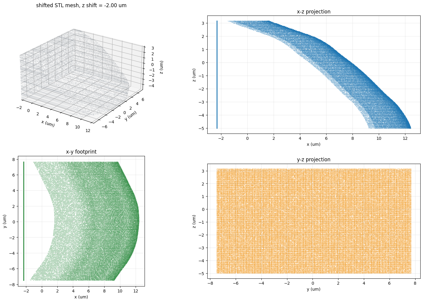
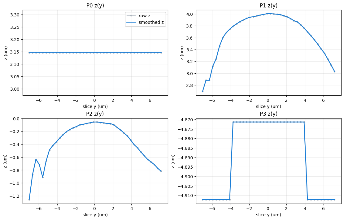
This cell first visualizes the shifted STL mesh, then extracts upper-envelope (x, z) curves at 40 fixed y positions and fits each one with a cubic Bezier curve. Because independent slice fits can be jagged across y, the raw control-point trajectories are smoothed along the slice direction with a second-difference regularizer before they are used as the initial design.
def chord_length_parameterize(points):
    deltas = np.diff(points, axis=0)
    distances = np.sqrt((deltas**2).sum(axis=1))
    cumulative = np.concatenate([[0.0], np.cumsum(distances)])
    return cumulative / cumulative[-1] if cumulative[-1] > 0 else cumulative


def bernstein_matrix(degree, t):
    basis = np.empty((len(t), degree + 1), dtype=float)
    for i in range(degree + 1):
        basis[:, i] = math.comb(degree, i) * (t**i) * ((1.0 - t) ** (degree - i))
    return basis


def fit_bezier_curve(points, degree=3):
    points = np.asarray(points, dtype=float)
    t = chord_length_parameterize(points)
    basis = bernstein_matrix(degree, t)

    control_points = np.zeros((degree + 1, 2), dtype=float)
    control_points[0] = points[0]
    control_points[-1] = points[-1]

    interior_basis = basis[:, 1:-1]
    fixed = np.outer(basis[:, 0], control_points[0]) + np.outer(basis[:, -1], control_points[-1])
    rhs = points - fixed
    control_points[1:-1, 0] = np.linalg.lstsq(interior_basis, rhs[:, 0], rcond=None)[0]
    control_points[1:-1, 1] = np.linalg.lstsq(interior_basis, rhs[:, 1], rcond=None)[0]
    return control_points


def eval_cubic_bezier(cp, u):
    u = anp.reshape(u, (-1,))
    cp = anp.reshape(cp, (4, 2))
    b0 = (1 - u) ** 3
    b1 = 3 * u * (1 - u) ** 2
    b2 = 3 * u**2 * (1 - u)
    b3 = u**3
    return b0[:, None] * cp[0] + b1[:, None] * cp[1] + b2[:, None] * cp[2] + b3[:, None] * cp[3]


def _resample_polyline(points, num_samples):
    points = np.asarray(points, dtype=float)
    deltas = np.diff(points, axis=0)
    arclen = np.concatenate([[0.0], np.cumsum(np.linalg.norm(deltas, axis=1))])
    if arclen[-1] <= 0:
        return np.repeat(points[:1], num_samples, axis=0)
    target = np.linspace(0, arclen[-1], num_samples)
    return np.column_stack([
        np.interp(target, arclen, points[:, 0]),
        np.interp(target, arclen, points[:, 1]),
    ])


def extract_slice_points(vertices_um, y_value, y_tol, num_samples):
    cloud = vertices_um[np.abs(vertices_um[:, 1] - y_value) <= y_tol]
    if len(cloud) < 80:
        return None

    x = cloud[:, 0]
    z = cloud[:, 2]
    bin_count = max(220, num_samples * 3)
    x_bins = np.linspace(x.min(), x.max(), bin_count + 1)
    bin_index = np.digitize(x, x_bins) - 1

    x_centers = []
    z_upper = []
    for idx in range(bin_count):
        in_bin = bin_index == idx
        if np.any(in_bin):
            x_centers.append(float(np.mean(x[in_bin])))
            z_upper.append(float(np.max(z[in_bin])))

    if len(x_centers) < 20:
        return None
    profile = np.column_stack([x_centers, z_upper])
    profile = profile[np.argsort(profile[:, 0])]
    return _resample_polyline(profile, num_samples)


def extract_surface_slices(vertices_um, bounds_um, slice_count, num_samples):
    y_min, y_max = bounds_um[0, 1], bounds_um[1, 1]
    y_span = y_max - y_min
    y_positions = np.linspace(y_min + 0.03 * y_span, y_max - 0.03 * y_span, slice_count)
    base_tol = max((y_positions[1] - y_positions[0]) * 0.45, y_span * 1e-3)

    valid_y = []
    slices = []
    for y_value in y_positions:
        pts = None
        for scale in (1.0, 1.8, 2.8):
            pts = extract_slice_points(vertices_um, y_value, base_tol * scale, num_samples)
            if pts is not None:
                break
        if pts is not None:
            valid_y.append(y_value)
            slices.append(pts)

    if len(slices) != slice_count:
        raise RuntimeError(f"Expected {slice_count} slices, extracted {len(slices)} valid slices.")
    return np.asarray(valid_y), slices


def second_difference_smooth_1d(values, smooth_lambda, fix_first_last=True):
    values = np.asarray(values, dtype=float)
    n = len(values)
    if smooth_lambda <= 0 or n < 4:
        return values.copy()

    d2 = np.zeros((n - 2, n), dtype=float)
    for i in range(n - 2):
        d2[i, i : i + 3] = (1.0, -2.0, 1.0)

    system = np.eye(n) + smooth_lambda * (d2.T @ d2)
    rhs = values.copy()
    if fix_first_last:
        pin_weight = 1e6
        system[0, 0] += pin_weight
        system[-1, -1] += pin_weight
        rhs[0] += pin_weight * values[0]
        rhs[-1] += pin_weight * values[-1]
    return np.linalg.solve(system, rhs)


def smooth_control_points_across_y(control_points_xz):
    smoothed = np.asarray(control_points_xz, dtype=float).copy()
    for point_index in range(4):
        smooth_lambda = SMOOTH_HANDLE_LAMBDA if point_index in (1, 2) else SMOOTH_ENDPOINT_LAMBDA
        for coord_index in range(2):
            smoothed[:, point_index, coord_index] = second_difference_smooth_1d(
                control_points_xz[:, point_index, coord_index],
                smooth_lambda=smooth_lambda,
                fix_first_last=SMOOTH_FIX_FIRST_LAST_SLICE,
            )
    return smoothed


def cross_slice_roughness(control_points_xz):
    d2 = np.diff(np.asarray(control_points_xz), n=2, axis=0)
    return float(np.sqrt(np.mean(d2**2)))


def plot_cross_slice_smoothing(slice_y_um, raw_cp, smooth_cp):
    fig, axes = plt.subplots(2, 2, figsize=(11, 7), constrained_layout=True)
    point_labels = ("P0", "P1", "P2", "P3")
    for ax, point_index in zip(axes.ravel(), range(4)):
        ax.plot(slice_y_um, raw_cp[:, point_index, 1], "o-", color="#adb5bd", linewidth=1.0, markersize=3, label="raw z")
        ax.plot(slice_y_um, smooth_cp[:, point_index, 1], "-", color="#1c7ed6", linewidth=2.0, label="smoothed z")
        ax.set_title(f"{point_labels[point_index]} z(y)")
        ax.set_xlabel("slice y (um)")
        ax.set_ylabel("z (um)")
        ax.grid(True, alpha=0.25)
    axes[0, 0].legend(loc="best")
    fig.savefig(RESULTS_DIR / "bezier_cross_slice_smoothing.png", dpi=180)
    plt.show()


def _subsample_indices(count, max_count, seed=0):
    if count <= max_count:
        return np.arange(count)
    rng = np.random.default_rng(seed)
    return np.sort(rng.choice(count, size=max_count, replace=False))


def _format_bounds(values):
    return f"[{values[0]:.3f}, {values[1]:.3f}]"


def plot_shifted_stl(vertices_um, faces, bounds_um, max_faces=18000, max_points=80000):
    from mpl_toolkits.mplot3d.art3d import Poly3DCollection

    faces = np.asarray(faces, dtype=int)
    face_idx = _subsample_indices(len(faces), max_faces, seed=1)
    point_idx = _subsample_indices(len(vertices_um), max_points, seed=2)
    triangles = vertices_um[faces[face_idx]]
    points = vertices_um[point_idx]

    fig = plt.figure(figsize=(15, 10), constrained_layout=True)
    ax3d = fig.add_subplot(2, 2, 1, projection="3d")
    ax_xz = fig.add_subplot(2, 2, 2)
    ax_xy = fig.add_subplot(2, 2, 3)
    ax_yz = fig.add_subplot(2, 2, 4)

    mesh_artist = Poly3DCollection(
        triangles,
        facecolor="#adb5bd",
        edgecolor="#495057",
        linewidths=0.03,
        alpha=0.80,
    )
    ax3d.add_collection3d(mesh_artist)
    ax3d.set_xlim(bounds_um[0, 0], bounds_um[1, 0])
    ax3d.set_ylim(bounds_um[0, 1], bounds_um[1, 1])
    ax3d.set_zlim(bounds_um[0, 2], bounds_um[1, 2])
    ax3d.set_box_aspect(bounds_um[1] - bounds_um[0])
    ax3d.view_init(elev=24, azim=-55)
    ax3d.set_xlabel("x (um)")
    ax3d.set_ylabel("y (um)")
    ax3d.set_zlabel("z (um)")
    ax3d.set_title(f"shifted STL mesh, z shift = {STL_Z_SHIFT_UM:.2f} um")

    ax_xz.scatter(points[:, 0], points[:, 2], s=0.5, color="#1f77b4", alpha=0.35, rasterized=True)
    ax_xz.set_xlabel("x (um)")
    ax_xz.set_ylabel("z (um)")
    ax_xz.set_title("x-z projection")
    ax_xz.set_aspect("equal", adjustable="box")

    ax_xy.scatter(points[:, 0], points[:, 1], s=0.5, color="#2b8a3e", alpha=0.35, rasterized=True)
    ax_xy.set_xlabel("x (um)")
    ax_xy.set_ylabel("y (um)")
    ax_xy.set_title("x-y footprint")
    ax_xy.set_aspect("equal", adjustable="box")

    ax_yz.scatter(points[:, 1], points[:, 2], s=0.5, color="#f08c00", alpha=0.35, rasterized=True)
    ax_yz.set_xlabel("y (um)")
    ax_yz.set_ylabel("z (um)")
    ax_yz.set_title("y-z projection")
    ax_yz.set_aspect("equal", adjustable="box")

    for ax in (ax_xz, ax_xy, ax_yz):
        ax.grid(True, alpha=0.25)

    fig.savefig(RESULTS_DIR / "stl_shifted_visualization.png", dpi=180)
    plt.show()


mesh_m = trimesh.load_mesh(STL_PATH, force="mesh")
vertices_um = np.asarray(mesh_m.vertices, dtype=float) * 1e6
vertices_um[:, 2] += STL_Z_SHIFT_UM
bounds_um = np.vstack([vertices_um.min(axis=0), vertices_um.max(axis=0)])
print(f"Applied STL z shift: {STL_Z_SHIFT_UM:.3f} um")
print(f"STL vertices: {len(vertices_um)}, faces: {len(mesh_m.faces)}")
print(
    "shifted STL bounds: "
    f"x={_format_bounds(bounds_um[:, 0])} um, "
    f"y={_format_bounds(bounds_um[:, 1])} um, "
    f"z={_format_bounds(bounds_um[:, 2])} um"
)
plot_shifted_stl(vertices_um, mesh_m.faces, bounds_um)

slice_y0_um, slice_points = extract_surface_slices(vertices_um, bounds_um, NUM_SLICES, NUM_PROFILE_POINTS)
control_points0_raw = np.stack([fit_bezier_curve(points, BEZIER_DEGREE) for points in slice_points], axis=0)
control_points0 = smooth_control_points_across_y(control_points0_raw) if SMOOTH_CONTROL_POINTS_ACROSS_Y else control_points0_raw.copy()

y_min0, y_max0 = slice_y0_um.min(), slice_y0_um.max()
raw_roughness = cross_slice_roughness(control_points0_raw)
smoothed_roughness = cross_slice_roughness(control_points0)
max_smoothing_delta = float(np.max(np.abs(control_points0 - control_points0_raw)))

print(f"control_points0 shape: {control_points0.shape}  # slices, 4 points, x/z")
print(f"fixed slice y positions: {slice_y0_um.shape}")
print(f"y span: {y_min0:.3f} to {y_max0:.3f} um")
print(f"cross-slice smoothing enabled: {SMOOTH_CONTROL_POINTS_ACROSS_Y}")
print(f"roughness raw -> smoothed: {raw_roughness:.6f} -> {smoothed_roughness:.6f}")
print(f"max smoothing delta: {max_smoothing_delta:.4f} um")
plot_cross_slice_smoothing(slice_y0_um, control_points0_raw, control_points0)
Applied STL z shift: -2.000 um
STL vertices: 96000, faces: 191996
shifted STL bounds: x=[-2.316, 12.416] um, y=[-7.476, 7.650] um, z=[-4.994, 3.146] um
control_points0 shape: (40, 4, 2)  # slices, 4 points, x/z
fixed slice y positions: (40,)
y span: -7.022 to 7.196 um
cross-slice smoothing enabled: False
roughness raw -> smoothed: 0.061321 -> 0.061321
max smoothing delta: 0.0000 um
Pack p and Define Bounds
p is a flat vector containing only the P1 and P2 Bezier handle coordinates. P0, P3, and all slice positions in y are fixed, so the reflector endpoint dimensions remain fixed during optimization.
OPTIMIZED_CONTROL_POINT_INDICES = (1, 2)


def pack_p(control_points_xz):
    control_points_xz = np.asarray(control_points_xz)
    return np.ravel(control_points_xz[:, OPTIMIZED_CONTROL_POINT_INDICES, :])


fixed_control_p0 = anp.array(control_points0[:, 0:1, :])
fixed_control_p3 = anp.array(control_points0[:, 3:4, :])


def unpack_p(p):
    handles = anp.reshape(p, (NUM_SLICES, len(OPTIMIZED_CONTROL_POINT_INDICES), 2))
    return anp.concatenate([fixed_control_p0, handles[:, 0:1, :], handles[:, 1:2, :], fixed_control_p3], axis=1)


p0 = pack_p(control_points0)

cp_min = control_points0.copy()
cp_max = control_points0.copy()
cp_min[:, OPTIMIZED_CONTROL_POINT_INDICES, 0] -= HANDLE_DX_BOUND_UM
cp_max[:, OPTIMIZED_CONTROL_POINT_INDICES, 0] += HANDLE_DX_BOUND_UM
cp_min[:, OPTIMIZED_CONTROL_POINT_INDICES, 1] -= HANDLE_DZ_BOUND_UM
cp_max[:, OPTIMIZED_CONTROL_POINT_INDICES, 1] += HANDLE_DZ_BOUND_UM

p_min = pack_p(cp_min)
p_max = pack_p(cp_max)

print(f"p length: {len(p0)} = 40 * 2 * 2 Bezier handle coordinates")
print(f"optimized points per slice: P1 and P2")
print(f"fixed points per slice: P0 and P3")
print(f"handle x/z bounds: +/-({HANDLE_DX_BOUND_UM}, {HANDLE_DZ_BOUND_UM}) um")
print("slice y positions are fixed and are not part of p")
p length: 160 = 40 * 2 * 2 Bezier handle coordinates
optimized points per slice: P1 and P2
fixed points per slice: P0 and P3
handle x/z bounds: +/-(2, 2) um
slice y positions are fixed and are not part of p
Visualize One Slice and Its Allowed Motion
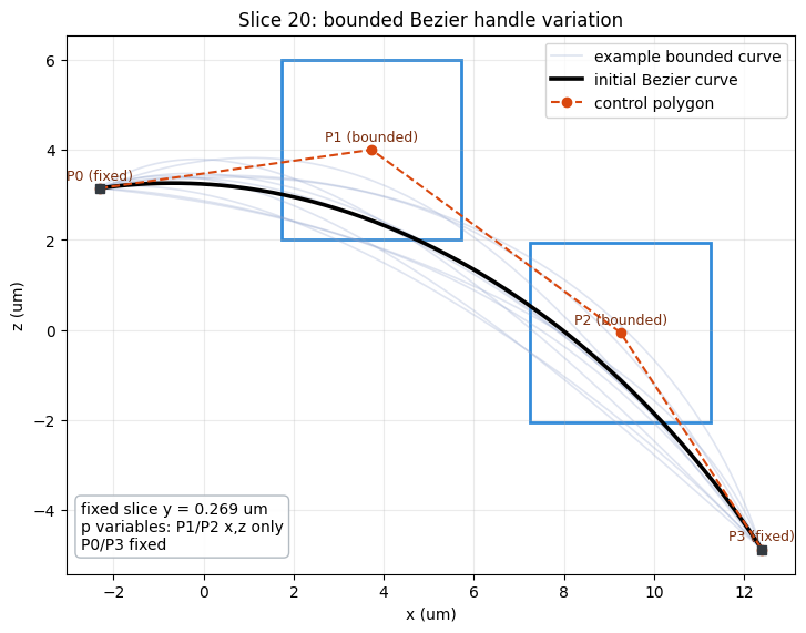
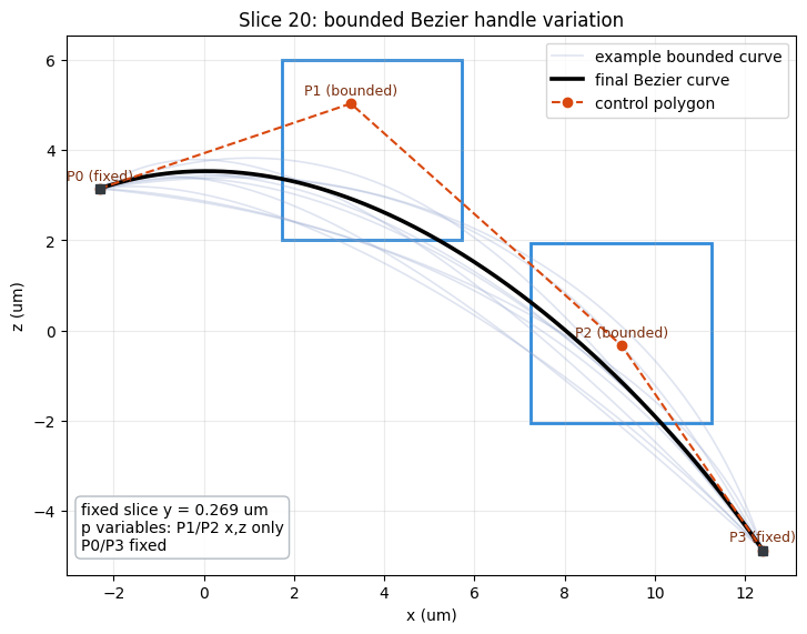
The full 40-slice plot is too dense for checking bounds. This example uses one middle slice and shows the initial cubic Bezier curve, fixed endpoints P0/P3, bounded handle points P1/P2, and several possible curves sampled inside those handle bounds.
EXAMPLE_SLICE_INDEX = NUM_SLICES // 2
def plot_single_slice_bounds(
    slice_index=EXAMPLE_SLICE_INDEX,
    control_points_xz=None,
    num_examples=10,
    random_seed=3,
    title_prefix="Initial",
):
    if control_points_xz is None:
        control_points_xz = control_points0

    cp = np.asarray(control_points_xz)[slice_index]
    cp_lo = cp_min[slice_index]
    cp_hi = cp_max[slice_index]
    y_val = slice_y0_um[slice_index]

    rng = np.random.default_rng(random_seed)
    u_plot = np.linspace(0.0, 1.0, 240)

    fig, ax = plt.subplots(figsize=(8.5, 5.6), constrained_layout=True)

    for example_idx in range(num_examples):
        cp_sample = cp.copy()
        for point_index in OPTIMIZED_CONTROL_POINT_INDICES:
            cp_sample[point_index] = cp_lo[point_index] + rng.random(2) * (cp_hi[point_index] - cp_lo[point_index])
        curve_sample = np.asarray(eval_cubic_bezier(cp_sample, u_plot))
        ax.plot(
            curve_sample[:, 0],
            curve_sample[:, 1],
            color="#8da0cb",
            alpha=0.28,
            linewidth=1.2,
            label="example bounded curve" if example_idx == 0 else None,
        )

    curve = np.asarray(eval_cubic_bezier(cp, u_plot))
    ax.plot(curve[:, 0], curve[:, 1], color="black", linewidth=2.6, label=f"{title_prefix.lower()} Bezier curve")
    ax.plot(cp[:, 0], cp[:, 1], "o--", color="#d9480f", linewidth=1.5, markersize=6, label="control polygon")

    point_labels = ["P0", "P1", "P2", "P3"]
    for j, label in enumerate(point_labels):
        if j in OPTIMIZED_CONTROL_POINT_INDICES:
            x0, z0 = cp_lo[j]
            x1, z1 = cp_hi[j]
            ax.add_patch(
                plt.Rectangle(
                    (x0, z0),
                    x1 - x0,
                    z1 - z0,
                    fill=False,
                    edgecolor="#1c7ed6",
                    linewidth=2.0,
                    alpha=0.9,
                )
            )
            suffix = "bounded"
        else:
            suffix = "fixed"
            ax.plot(cp[j, 0], cp[j, 1], marker="s", color="#343a40", markersize=6)
        ax.text(cp[j, 0], cp[j, 1] + 0.12, f"{label} ({suffix})", ha="center", va="bottom", fontsize=9, color="#7a2e0e")

    info = f"fixed slice y = {y_val:.3f} um\np variables: P1/P2 x,z only\nP0/P3 fixed"
    ax.text(
        0.02,
        0.04,
        info,
        transform=ax.transAxes,
        ha="left",
        va="bottom",
        bbox={"boxstyle": "round,pad=0.35", "facecolor": "white", "edgecolor": "#adb5bd", "alpha": 0.92},
    )

    ax.set_title(f"Slice {slice_index}: bounded Bezier handle variation")
    ax.set_xlabel("x (um)")
    ax.set_ylabel("z (um)")
    ax.set_aspect("equal", adjustable="box")
    ax.legend(loc="best")

    print(f"Slice index: {slice_index}")
    print(f"Fixed y: {y_val:.4f} um")
    print("Control-point status for this slice:")
    for j, label in enumerate(point_labels):
        if j in OPTIMIZED_CONTROL_POINT_INDICES:
            print(
                f"  {label}: x [{cp_lo[j, 0]:.4f}, {cp_hi[j, 0]:.4f}] um, "
                f"z [{cp_lo[j, 1]:.4f}, {cp_hi[j, 1]:.4f}] um"
            )
        else:
            print(f"  {label}: fixed at x {cp[j, 0]:.4f} um, z {cp[j, 1]:.4f} um")
    fig.savefig(RESULTS_DIR / "bezier_single_slice_bounds.png", dpi=180)
    plt.show()


plot_single_slice_bounds()
Slice index: 20
Fixed y: 0.2695 um
Control-point status for this slice:
  P0: fixed at x -2.3158 um, z 3.1465 um
  P1: x [1.7292, 5.7292] um, z [2.0032, 6.0032] um
  P2: x [7.2543, 11.2543] um, z [-2.0561, 1.9439] um
  P3: fixed at x 12.3950 um, z -4.8714 um
Convert Bezier Slices to Tidy3D Shape Structures
The optimizer controls 40 Bezier slices. Each slice is converted to a closed polygon (Bezier top curve plus flat base) and extruded as a single td.PolySlab spanning its y edge interval. For STL export, the 40 control-point sets are interpolated onto a denser y grid to produce a smoother lofted mesh.
def clip_p_to_bounds(p):
    return anp.minimum(anp.maximum(p, p_min), p_max)


def fixed_y_edges_from_slice_y(slice_y):
    mids = 0.5 * (slice_y[:-1] + slice_y[1:])
    first = slice_y[0] - 0.5 * (slice_y[1] - slice_y[0])
    last = slice_y[-1] + 0.5 * (slice_y[-1] - slice_y[-2])
    return np.concatenate([[first], mids, [last]])


design_y_edges_um = fixed_y_edges_from_slice_y(slice_y0_um)
reflector_y_min_um = design_y_edges_um[0]
reflector_y_max_um = design_y_edges_um[-1]
z_base_um = bounds_um[0, 2] - 0.30
u_poly = np.linspace(0.0, 1.0, NUM_POLYGON_POINTS)

print(f"design slices optimized: {NUM_SLICES}")
print(f"design p length: {len(p0)}")
print(f"design y spacing: {np.diff(design_y_edges_um).mean():.4f} um")


def polygon_from_control_points(cp):
    top = eval_cubic_bezier(cp, u_poly)
    right_base = anp.reshape(anp.stack([top[-1, 0], 0.0 * top[-1, 0] + z_base_um]), (1, 2))
    left_base = anp.reshape(anp.stack([top[0, 0], 0.0 * top[0, 0] + z_base_um]), (1, 2))
    return anp.vstack([top, right_base, left_base])


def make_reflector_structures_from_p(p):
    control_points_xz = unpack_p(p)

    structures = []
    for idx in range(NUM_SLICES):
        vertices_xz = polygon_from_control_points(control_points_xz[idx])
        geom = td.PolySlab(vertices=vertices_xz, axis=1, slab_bounds=(design_y_edges_um[idx], design_y_edges_um[idx + 1]))
        structures.append(
            td.Structure(
                geometry=geom,
                medium=reflector_medium,
                background_medium=background_medium,
                name=f"reflector_slice_{idx:03d}",
            )
        )
    return structures


def make_tip_structure():
    return td.Structure(
        geometry=td.Box(
            center=(tip_x_center_um, tip_y_um, tip_z_um),
            size=(TIP_LENGTH_UM, TIP_SIZE_UM, TIP_SIZE_UM),
        ),
        medium=tip_medium,
        name="horizontal_sin_tip",
    )


reflector_structures0 = make_reflector_structures_from_p(p0)
print(f"Created {len(reflector_structures0)} Bezier PolySlab reflector structures.")
design slices optimized: 40
design p length: 160
design y spacing: 0.3646 um
Created 40 Bezier PolySlab reflector structures.
Build Tidy3D Simulation
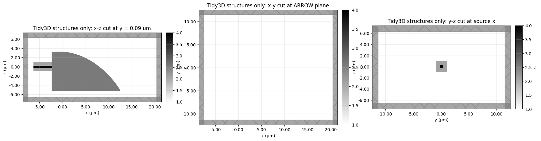
The global background is air. The SiN waveguide tip is modeled as a visible horizontal td.Box, and it is embedded inside an explicit SiO2 cladding box. The SiN and cladding right edges end at the fitted reflector's left side, their y position is the reflector center, and their z position is fixed by WAVEGUIDE_Z_UM = 0 um. The ModeSource is an expanded x-normal source through the cladded tip region launching in +x.
Because the 480 nm by 480 nm tip is the taper end and should not be treated as a long propagating waveguide section, the source plane is placed close to the reflector-side tip end using TIP_SOURCE_GAP_FROM_REFLECTOR_UM.
The imported STL reflector is shifted by STL_Z_SHIFT_UM = -2 um. The ARROW target monitor is an x-y plane normal to z, underneath the reflector. Its z location is computed as close as possible below the reflector bottom: z_base_um - ARROW_MONITOR_GAP_UM. No separate ARROW waveguide material box is used because its index is close to air; the output monitor samples the air-background region. Its aperture is shifted in x so the aperture center is ARROW_CENTER_X_UM = 9 um.
arrow_peak_idx = np.unravel_index(np.argmax(arrow["field_xy"]), arrow["field_xy"].shape)
arrow_peak_file_y_um = float(arrow["y_um"][arrow_peak_idx[1]])

# Horizontal SiN tip placement.
# P0 is the fixed fitted left endpoint for each Bezier slice; use the central slice for z.
tip_y_um = 0.5 * (slice_y0_um.min() + slice_y0_um.max())
left_edge_x_um = float(np.median(control_points0[:, 0, 0]))
left_edge_z_um = float(control_points0[EXAMPLE_SLICE_INDEX, 0, 1])
tip_x_end_um = left_edge_x_um
tip_x_start_um = tip_x_end_um - TIP_LENGTH_UM
tip_x_center_um = 0.5 * (tip_x_start_um + tip_x_end_um)
tip_z_um = WAVEGUIDE_Z_UM
source_x_um = tip_x_end_um - TIP_SOURCE_GAP_FROM_REFLECTOR_UM

# Map the 2D ARROW target into simulation x-y coordinates.
# x is shifted so the aperture geometric center is ARROW_CENTER_X_UM; y peak aligns to the centered tip y.
arrow_raw_x_center_um = 0.5 * (arrow["x_um"].min() + arrow["x_um"].max())
arrow_x_shift_um = ARROW_CENTER_X_UM - arrow_raw_x_center_um
arrow_x_profile_um = arrow["x_um"] + arrow_x_shift_um
arrow_y_profile_um = arrow["y_um"] - arrow_peak_file_y_um + tip_y_um
arrow_xmin, arrow_xmax = arrow_x_profile_um.min(), arrow_x_profile_um.max()
arrow_ymin, arrow_ymax = arrow_y_profile_um.min(), arrow_y_profile_um.max()
reflector_bottom_z_um = z_base_um
arrow_output_z_um = reflector_bottom_z_um - ARROW_MONITOR_GAP_UM
arrow_center = (0.5 * (arrow_xmin + arrow_xmax), 0.5 * (arrow_ymin + arrow_ymax), arrow_output_z_um)
arrow_size = (arrow_xmax - arrow_xmin, arrow_ymax - arrow_ymin, 0.0)

print(f"tip end x = {tip_x_end_um:.4f} um, starts at x = {tip_x_start_um:.4f} um")
print(f"tip center y = {tip_y_um:.4f} um")
print(f"tip / waveguide z = {tip_z_um:.4f} um")
print(f"SiN tip size = {TIP_SIZE_UM:.4f} um square, SiO2 cladding size = {TIP_CLADDING_SIZE_UM:.4f} um square")
print(f"mode source size = {MODE_SOURCE_SIZE_Y_UM:.4f} um by {MODE_SOURCE_SIZE_Z_UM:.4f} um")
print(f"source plane x = {source_x_um:.4f} um, direction = {SOURCE_DIRECTION}x")
print(f"source gap from reflector-side tip end = {TIP_SOURCE_GAP_FROM_REFLECTOR_UM:.4f} um")
print(f"reflector bottom z = {reflector_bottom_z_um:.4f} um")
print(f"ARROW FOM monitor is x-y at z = {arrow_output_z_um:.4f} um")
print(f"ARROW monitor gap below reflector bottom = {ARROW_MONITOR_GAP_UM:.4f} um")
print("No separate ARROW waveguide material box is used; the output region is air background.")
print(f"ARROW aperture center x = {0.5 * (arrow_xmin + arrow_xmax):.4f} um")
print(f"ARROW x shift = {arrow_x_shift_um:.4f} um")
print(f"ARROW FOM x range = [{arrow_xmin:.4f}, {arrow_xmax:.4f}] um")
print(f"ARROW FOM y range = [{arrow_ymin:.4f}, {arrow_ymax:.4f}] um")

source = td.ModeSource(
    center=(source_x_um, tip_y_um, tip_z_um),
    size=(0.0, MODE_SOURCE_SIZE_Y_UM, MODE_SOURCE_SIZE_Z_UM),
    source_time=td.GaussianPulse(freq0=freq0, fwidth=freqw),
    mode_spec=td.ModeSpec(num_modes=1, target_neff=n_tip),
    mode_index=0,
    direction=SOURCE_DIRECTION,
    num_freqs=1,
)

fom_monitor = td.FieldMonitor(
    name=FOM_MONITOR_NAME,
    center=arrow_center,
    size=arrow_size,
    freqs=[freq0],
    fields=E_FIELD_COMPONENTS,
    colocate=True,
)

field_monitor_xy = td.FieldMonitor(
    name="field_xy",
    center=arrow_center,
    size=arrow_size,
    freqs=[freq0],
    fields=E_FIELD_COMPONENTS,
    colocate=True,
)

field_xmin = min(tip_x_start_um, arrow_xmin)
field_xmax = max(tip_x_end_um, arrow_xmax)
field_zmin = min(tip_z_um - MODE_SOURCE_SIZE_Z_UM / 2, arrow_output_z_um)
field_zmax = max(tip_z_um + MODE_SOURCE_SIZE_Z_UM / 2, arrow_output_z_um)
field_monitor_xz = td.FieldMonitor(
    name="field_xz",
    center=(0.5 * (field_xmin + field_xmax), tip_y_um, 0.5 * (field_zmin + field_zmax)),
    size=(field_xmax - field_xmin, 0.0, field_zmax - field_zmin),
    freqs=[freq0],
    fields=E_FIELD_COMPONENTS,
)

opt_xmin = bounds_um[0, 0] - OPT_FIELDS_BUFFER_UM
opt_xmax = bounds_um[1, 0] + OPT_FIELDS_BUFFER_UM
opt_ymin = reflector_y_min_um - OPT_FIELDS_BUFFER_UM
opt_ymax = reflector_y_max_um + OPT_FIELDS_BUFFER_UM
opt_zmin = z_base_um - OPT_FIELDS_BUFFER_UM
opt_zmax = bounds_um[1, 2] + OPT_FIELDS_BUFFER_UM
opt_fields_center = tuple(float(v) for v in (0.5 * (opt_xmin + opt_xmax), 0.5 * (opt_ymin + opt_ymax), 0.5 * (opt_zmin + opt_zmax)))
opt_fields_size = tuple(float(v) for v in (opt_xmax - opt_xmin, opt_ymax - opt_ymin, opt_zmax - opt_zmin))
opt_fields_monitor = td.FieldMonitor(
    name=OPT_FIELDS_MONITOR_NAME,
    center=opt_fields_center,
    size=opt_fields_size,
    freqs=[freq0],
    fields=E_FIELD_COMPONENTS,
    colocate=True,
)

print(f"opt_fields monitor center: {opt_fields_center}")
print(f"opt_fields monitor size:   {opt_fields_size}")


def make_tip_cladding_structure():
    return td.Structure(
        geometry=td.Box(
            center=(tip_x_center_um, tip_y_um, tip_z_um),
            size=(TIP_LENGTH_UM, TIP_CLADDING_SIZE_UM, TIP_CLADDING_SIZE_UM),
        ),
        medium=sio2_medium,
        name="sio2_tip_cladding",
    )


def make_sim(p, include_diagnostics=False):
    reflector_structures = make_reflector_structures_from_p(p)
    tip_cladding_structure = make_tip_cladding_structure()
    tip_structure = make_tip_structure()

    x_min = min(bounds_um[0, 0] - HANDLE_DX_BOUND_UM, arrow_xmin, tip_x_start_um) - pml_buffer_um
    x_max = max(bounds_um[1, 0] + HANDLE_DX_BOUND_UM, arrow_xmax, tip_x_end_um) + pml_buffer_um
    y_min = min(reflector_y_min_um, arrow_ymin, tip_y_um - TIP_CLADDING_SIZE_UM / 2, tip_y_um - MODE_SOURCE_SIZE_Y_UM / 2) - pml_buffer_um
    y_max = max(reflector_y_max_um, arrow_ymax, tip_y_um + TIP_CLADDING_SIZE_UM / 2, tip_y_um + MODE_SOURCE_SIZE_Y_UM / 2) + pml_buffer_um
    z_min = min(z_base_um, arrow_output_z_um, tip_z_um - TIP_CLADDING_SIZE_UM / 2, tip_z_um - MODE_SOURCE_SIZE_Z_UM / 2) - pml_buffer_um
    z_max = max(bounds_um[1, 2] + HANDLE_DZ_BOUND_UM, arrow_output_z_um, tip_z_um + TIP_CLADDING_SIZE_UM / 2, tip_z_um + MODE_SOURCE_SIZE_Z_UM / 2) + pml_buffer_um

    sim_center = ((x_min + x_max) / 2, (y_min + y_max) / 2, (z_min + z_max) / 2)
    sim_size = (x_max - x_min, y_max - y_min, z_max - z_min)

    monitors = [fom_monitor]
    if include_diagnostics:
        monitors.extend([field_monitor_xy, field_monitor_xz, opt_fields_monitor])

    return td.Simulation(
        center=sim_center,
        size=sim_size,
        medium=background_medium,
        structures=[tip_cladding_structure, tip_structure] + reflector_structures,
        sources=[source],
        monitors=monitors,
        run_time=run_time_factor / freqw,
        grid_spec=td.GridSpec.auto(wavelength=lambda0_um, min_steps_per_wvl=min_steps_per_wvl),
        boundary_spec=td.BoundarySpec.all_sides(boundary=td.PML()),
    )


sim0 = make_sim(p0, include_diagnostics=True)
print(f"Simulation size: {sim0.size}")
print(f"Structures: {len(sim0.structures)}")
print(f"Diagnostic monitors: {[mnt.name for mnt in sim0.monitors]}")
tip end x = -2.3158 um, starts at x = -6.3158 um
tip center y = 0.0872 um
tip / waveguide z = 0.0000 um
SiN tip size = 0.4800 um square, SiO2 cladding size = 2.0000 um square
mode source size = 3.0000 um by 3.0000 um
source plane x = -2.6158 um, direction = +x
source gap from reflector-side tip end = 0.3000 um
reflector bottom z = -5.2941 um
ARROW FOM monitor is x-y at z = -5.3441 um
ARROW monitor gap below reflector bottom = 0.0500 um
No separate ARROW waveguide material box is used; the output region is air background.
ARROW aperture center x = 9.0000 um
ARROW x shift = 9.0000 um
ARROW FOM x range = [-1.1927, 19.1927] um
ARROW FOM y range = [-10.1055, 10.2799] um
opt_fields monitor center: (5.050339609624643, 0.0871873453434091, -1.073800490047142)
opt_fields monitor size:   (15.432229601577273, 15.282913774155222, 9.140593536154483)
Simulation size: (27.90849620382303, 22.785442025318076, 12.890593536154483)
Structures: 42
Diagnostic monitors: ['arrow_match', 'field_xy', 'field_xz', 'opt_fields']
# Plot the geometry and the simulation setup separately using Tidy3D's own plotting.


def plot_tidy3d_cuts(source_alpha, monitor_alpha, title_prefix, file_name):
    fig, axes = plt.subplots(1, 3, figsize=(17, 4.8), constrained_layout=True)

    sim0.plot_eps(
        y=tip_y_um,
        freq=freq0,
        ax=axes[0],
        source_alpha=source_alpha,
        monitor_alpha=monitor_alpha,
    )
    axes[0].set_title(f"{title_prefix}: x-z cut at y = {tip_y_um:.2f} um")

    sim0.plot_eps(
        z=arrow_output_z_um,
        freq=freq0,
        ax=axes[1],
        source_alpha=source_alpha,
        monitor_alpha=monitor_alpha,
    )
    axes[1].set_title(f"{title_prefix}: x-y cut at ARROW plane")

    sim0.plot_eps(
        x=source_x_um,
        freq=freq0,
        ax=axes[2],
        source_alpha=source_alpha,
        monitor_alpha=monitor_alpha,
    )
    axes[2].set_title(f"{title_prefix}: y-z cut at source x")

    fig.savefig(RESULTS_DIR / file_name, dpi=180)
    plt.show()


plot_tidy3d_cuts(
    source_alpha=0.0,
    monitor_alpha=0.0,
    title_prefix="Tidy3D structures only",
    file_name="tidy3d_structures_only.png",
)

plot_tidy3d_cuts(
    source_alpha=0.7,
    monitor_alpha=0.7,
    title_prefix="Tidy3D simulation setup",
    file_name="tidy3d_simulation_setup.png",
)

Scalar ARROW FOM
This FOM compares the simulated scalar electric-field magnitude |E| = sqrt(|Ex|^2 + |Ey|^2 + |Ez|^2) on the ARROW plane against the scalar ARROW target profile. It is a scalar overlap, not yet a full vector mode-overlap calculation.
arrow_target_da = xr.DataArray(
    arrow["field_xy"],
    coords={"x": arrow_x_profile_um, "y": arrow_y_profile_um},
    dims=("x", "y"),
)


def _target_on_monitor_grid(field_on_plane):
    x_grid = np.asarray(field_on_plane.coords["x"].values, dtype=float)
    y_grid = np.asarray(field_on_plane.coords["y"].values, dtype=float)
    target_interp = arrow_target_da.interp(x=x_grid, y=y_grid).fillna(0.0)
    return np.asarray(target_interp.values, dtype=float)


def electric_field_magnitude_on_monitor(sim_data, monitor_name, dims_order=None):
    e2 = None
    template = None
    monitor_data = sim_data[monitor_name]

    for component_name in E_FIELD_COMPONENTS:
        component = monitor_data.field_components[component_name]
        component = component.sel(f=freq0, method="nearest").squeeze(drop=True)
        if dims_order is not None:
            component = component.transpose(*dims_order)
        elif {"x", "y"}.issubset(component.dims):
            component = component.transpose("x", "y")

        values = component.values
        component_e2 = anp.abs(values) ** 2
        e2 = component_e2 if e2 is None else e2 + component_e2
        if template is None:
            template = component

    return anp.sqrt(e2), template


def electric_field_magnitude_dataarray(sim_data, monitor_name, dims_order=None):
    magnitude, template = electric_field_magnitude_on_monitor(sim_data, monitor_name, dims_order=dims_order)
    coords = {dim: template.coords[dim] for dim in template.dims}
    return xr.DataArray(np.asarray(magnitude), coords=coords, dims=template.dims)


def measure_arrow_profile_match(sim_data):
    simulated, field_on_plane = electric_field_magnitude_on_monitor(
        sim_data, FOM_MONITOR_NAME, dims_order=("x", "y")
    )
    target = anp.array(_target_on_monitor_grid(field_on_plane))

    eps = 1e-18
    target = target / anp.sqrt(anp.sum(anp.abs(target) ** 2) + eps)
    simulated = simulated / anp.sqrt(anp.sum(anp.abs(simulated) ** 2) + eps)
    overlap = anp.sum(anp.conj(target) * simulated)
    return anp.real(anp.conj(overlap) * overlap)


def objective(p, step_num=0, verbose=False):
    p = clip_p_to_bounds(p)
    sim = make_sim(p, include_diagnostics=False)
    sim_data = web.run(
        sim,
        task_name=f"bezier_reflector_arrow_step_{step_num:03d}",
        path=str(RESULTS_DIR / f"bezier_reflector_arrow_step_{step_num:03d}.hdf5"),
        verbose=verbose,
    )
    return measure_arrow_profile_match(sim_data)


objective_and_grad = value_and_grad(objective)
print(f"Scalar FOM uses x-y monitor '{FOM_MONITOR_NAME}' and total electric-field magnitude |E| from {E_FIELD_COMPONENTS}.")
Scalar FOM uses x-y monitor 'arrow_match' and total electric-field magnitude |E| from ('Ex', 'Ey', 'Ez').
RUN_COST_ESTIMATE = True

if RUN_COST_ESTIMATE:
    cost_sim = make_sim(p0, include_diagnostics=False)
    task_id = web.upload(cost_sim, task_name="bezier_reflector_arrow_cost_check", verbose=False)
    estimated_cost = web.estimate_cost(task_id)
    print(f"Estimated cost: {estimated_cost:.4f} FlexCredits")
else:
    print("Set RUN_COST_ESTIMATE = True after geometry plots are approved.")
16:33:16 EDT Estimated FlexCredit cost: 0.650. Minimum cost depends on task
             execution details. Use 'web.real_cost(task_id)' to get the billed
             FlexCredit cost after a simulation run.
Estimated cost: 0.6499 FlexCredits
RUN_OPTIMIZATION = True

num_steps = 40
learning_rate = 0.3

# Lightweight visualization uses optimization data already computed each step.
VISUALIZE_OPTIMIZATION = True
VISUALIZE_OPTIMIZATION_EVERY = 1

# Optional field diagnostics require extra cloud simulations. Keep False unless the cost is intentional.
RUN_DIAGNOSTIC_FIELDS_DURING_OPTIMIZATION = False
DIAGNOSTIC_FIELDS_EVERY = 5


def _as_numpy_control_points(p_current):
    return np.asarray(unpack_p(np.asarray(p_current, dtype=float)), dtype=float)


def _handle_array_from_p(p_current):
    return np.asarray(p_current, dtype=float).reshape(NUM_SLICES, len(OPTIMIZED_CONTROL_POINT_INDICES), 2)


def plot_handle_movement_progress(step, p_current):
    handle_delta = _handle_array_from_p(p_current - p0)

    fig, ax = plt.subplots(figsize=(7, 5), constrained_layout=True)
    labels = ("P1", "P2")
    for handle_idx, label in enumerate(labels):
        ax.plot(slice_y0_um, handle_delta[:, handle_idx, 0], "-", linewidth=1.5, label=f"{label}.x")
        ax.plot(slice_y0_um, handle_delta[:, handle_idx, 1], "--", linewidth=1.5, label=f"{label}.z")
    ax.axhline(0.0, color="black", linewidth=0.8)
    ax.set_xlabel("slice y (um)")
    ax.set_ylabel("offset from initial (um)")
    ax.set_title(f"optimized handle movement, step {step:03d}")
    ax.legend(loc="best", fontsize=8, ncol=2)
    ax.grid(True, alpha=0.25)
    fig.savefig(RESULTS_DIR / f"handle_movement_step_{step:03d}.png", dpi=180)
    fig.savefig(RESULTS_DIR / "handle_movement_latest.png", dpi=180)
    plt.show()


def plot_reflector_optimization_progress(step, p_current, J_history, grad_norm_history, update_norm_history):
    cp_current = _as_numpy_control_points(p_current)
    handle_delta = _handle_array_from_p(p_current - p0)
    bound_half_width = _handle_array_from_p((p_max - p_min) / 2)
    normalized_delta = np.divide(
        handle_delta,
        bound_half_width,
        out=np.zeros_like(handle_delta),
        where=bound_half_width > 0,
    )
    max_bound_usage = float(np.max(np.abs(normalized_delta)))

    fig, axes = plt.subplots(2, 2, figsize=(13, 9), constrained_layout=True)
    axes = axes.ravel()
    u_plot = np.linspace(0.0, 1.0, 180)
    slice_indices = np.unique(np.linspace(0, NUM_SLICES - 1, min(7, NUM_SLICES), dtype=int))
    colors = plt.cm.viridis(np.linspace(0.0, 1.0, len(slice_indices)))

    for color, slice_index in zip(colors, slice_indices):
        curve0 = np.asarray(eval_cubic_bezier(control_points0[slice_index], u_plot))
        curve_current = np.asarray(eval_cubic_bezier(cp_current[slice_index], u_plot))
        axes[0].plot(curve0[:, 0], curve0[:, 1], color="#adb5bd", linewidth=1.0, alpha=0.75)
        axes[0].plot(
            curve_current[:, 0],
            curve_current[:, 1],
            color=color,
            linewidth=1.8,
            label=f"y={slice_y0_um[slice_index]:.2f} um",
        )
    axes[0].set_aspect("equal", adjustable="box")
    axes[0].set_xlabel("x (um)")
    axes[0].set_ylabel("z (um)")
    axes[0].set_title("Bezier reflector slices: gray initial, color current")
    axes[0].legend(loc="best", fontsize=7)

    if J_history:
        axes[1].plot(np.arange(1, len(J_history) + 1), J_history, "o-", color="#1c7ed6")
    axes[1].set_xlabel("evaluated step")
    axes[1].set_ylabel("FOM")
    axes[1].set_title("scalar ARROW |E| profile match")
    axes[1].grid(True, alpha=0.25)

    labels = ("P1", "P2")
    for handle_idx, label in enumerate(labels):
        axes[2].plot(slice_y0_um, handle_delta[:, handle_idx, 0], "-", linewidth=1.5, label=f"{label}.x")
        axes[2].plot(slice_y0_um, handle_delta[:, handle_idx, 1], "--", linewidth=1.5, label=f"{label}.z")
    axes[2].axhline(0.0, color="black", linewidth=0.8)
    axes[2].set_xlabel("slice y (um)")
    axes[2].set_ylabel("offset from initial (um)")
    axes[2].set_title("optimized handle movement")
    axes[2].legend(loc="best", fontsize=8, ncol=2)
    axes[2].grid(True, alpha=0.25)

    if grad_norm_history:
        axes[3].semilogy(np.arange(1, len(grad_norm_history) + 1), grad_norm_history, "o-", label="grad norm")
    if update_norm_history:
        axes[3].semilogy(np.arange(1, len(update_norm_history) + 1), update_norm_history, "s-", label="update norm")
    axes[3].axhline(max(max_bound_usage, 1e-16), color="#f08c00", linestyle=":", label="max bound usage")
    axes[3].set_xlabel("step")
    axes[3].set_title(f"optimizer scales, max bound usage = {max_bound_usage:.3f}")
    axes[3].legend(loc="best", fontsize=8)
    axes[3].grid(True, alpha=0.25)

    latest_j = J_history[-1] if J_history else np.nan
    fig.suptitle(f"Bezier reflector inverse-design progress: step {step:03d}, FOM={latest_j:.6e}")
    fig.savefig(RESULTS_DIR / f"optimization_step_{step:03d}.png", dpi=180)
    fig.savefig(RESULTS_DIR / "optimization_latest.png", dpi=180)
    plt.show()


def plot_iteration_field_diagnostics(step, sim_data):
    field_xy_e = electric_field_magnitude_dataarray(sim_data, "field_xy", dims_order=("x", "y"))
    field_xz_e = electric_field_magnitude_dataarray(sim_data, "field_xz", dims_order=("x", "z"))
    fom_e = electric_field_magnitude_dataarray(sim_data, FOM_MONITOR_NAME, dims_order=("x", "y"))

    fig, axes = plt.subplots(1, 3, figsize=(16, 4), constrained_layout=True)
    field_xy_e.T.plot(ax=axes[0], cmap="magma")
    axes[0].set_title(f"step {step:03d}: |E| x-y diagnostic")
    field_xz_e.T.plot(ax=axes[1], cmap="magma")
    axes[1].set_title(f"step {step:03d}: |E| x-z slice")
    fom_e.T.plot(ax=axes[2], cmap="magma")
    axes[2].set_title(f"step {step:03d}: |E| ARROW plane")
    fig.savefig(RESULTS_DIR / f"optimization_fields_step_{step:03d}.png", dpi=180)
    plt.show()


p = p0.copy()
J_history = []
grad_norm_history = []
update_norm_history = []
p_history = [p.copy()]

if RUN_OPTIMIZATION:
    from tidy3d.plugins.autograd import adam, apply_updates

    optimizer = adam(learning_rate=learning_rate)
    opt_state = optimizer.init(p)

    for step in range(1, num_steps + 1):
        p_eval = np.array(p)
        value, grad = objective_and_grad(p_eval, step_num=step, verbose=False)
        grad = np.asarray(grad, dtype=float)
        grad_norm = float(np.linalg.norm(grad))

        updates, opt_state = optimizer.update(-grad, opt_state, p_eval)  # negative gradient because we maximize J
        p_next = apply_updates(p_eval, updates)
        p_next = clip_p_to_bounds(p_next)
        update_norm = float(np.linalg.norm(np.asarray(p_next) - p_eval))

        J_history.append(float(value))
        grad_norm_history.append(grad_norm)
        update_norm_history.append(update_norm)
        p_history.append(np.array(p_next))

        print(
            f"step={step:03d} J={float(value):.6e} "
            f"grad_norm={grad_norm:.6e} update_norm={update_norm:.6e}"
        )

        if VISUALIZE_OPTIMIZATION and step % VISUALIZE_OPTIMIZATION_EVERY == 0:
            plot_handle_movement_progress(step, np.asarray(p_next))

        if RUN_DIAGNOSTIC_FIELDS_DURING_OPTIMIZATION and step % DIAGNOSTIC_FIELDS_EVERY == 0:
            sim_diag = make_sim(np.asarray(p_next), include_diagnostics=True)
            sim_data_diag = web.run(
                sim_diag,
                task_name=f"bezier_reflector_arrow_diagnostic_step_{step:03d}",
                path=str(RESULTS_DIR / f"bezier_reflector_arrow_diagnostic_step_{step:03d}.hdf5"),
                verbose=False,
            )
            plot_iteration_field_diagnostics(step, sim_data_diag)

        p = np.asarray(p_next)

    if VISUALIZE_OPTIMIZATION:
        plot_reflector_optimization_progress(step, np.asarray(p), J_history, grad_norm_history, update_norm_history)
else:
    print("Set RUN_OPTIMIZATION = True only after cost approval.")
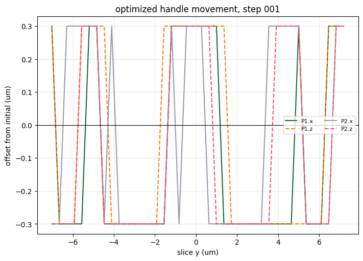
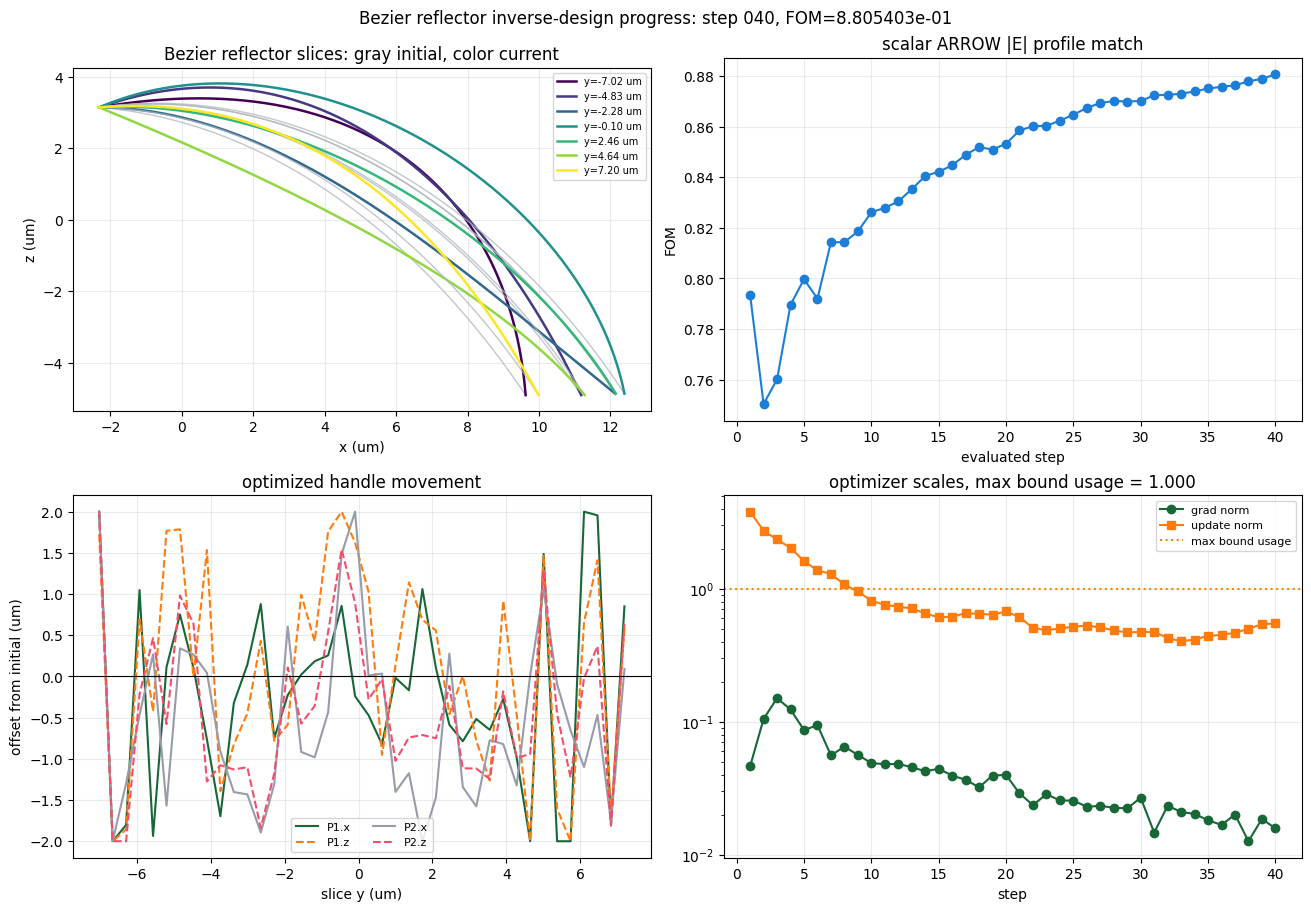
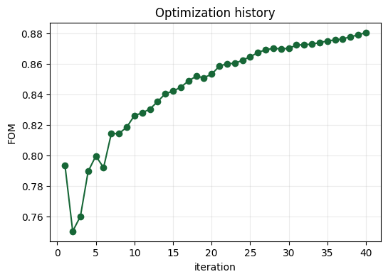
step=001 J=7.934480e-01 grad_norm=4.617260e-02 update_norm=3.794628e+00
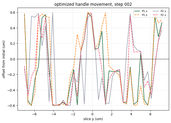
step=002 J=7.503974e-01 grad_norm=1.049166e-01 update_norm=2.721769e+00
step=003 J=7.601674e-01 grad_norm=1.500243e-01 update_norm=2.344832e+00
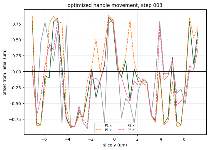
step=004 J=7.895896e-01 grad_norm=1.235064e-01 update_norm=2.022401e+00
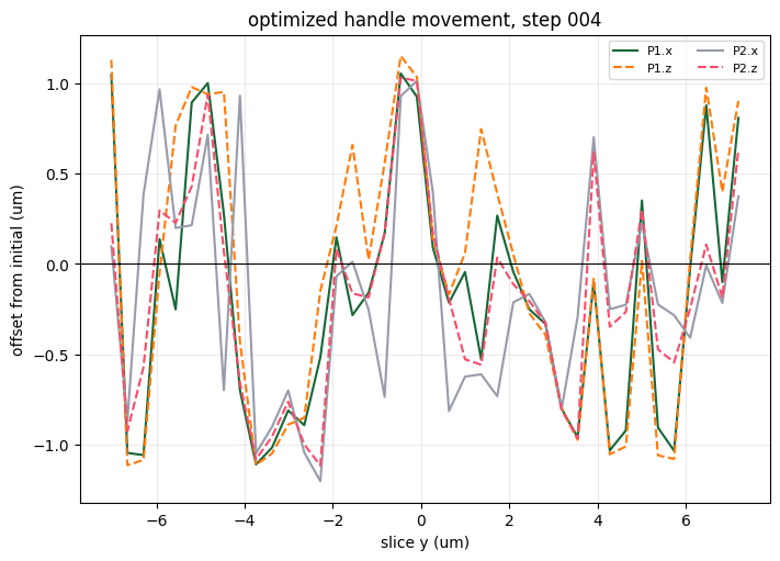
step=005 J=7.996861e-01 grad_norm=8.648625e-02 update_norm=1.612853e+00
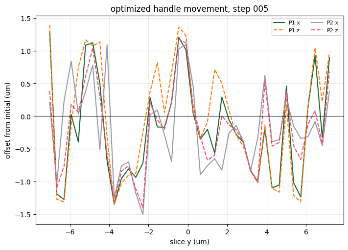
step=006 J=7.920200e-01 grad_norm=9.408350e-02 update_norm=1.373464e+00
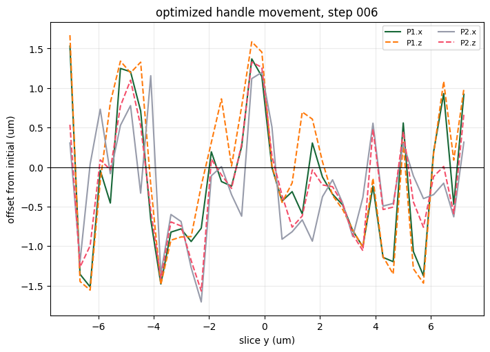
step=007 J=8.142797e-01 grad_norm=5.575307e-02 update_norm=1.287180e+00
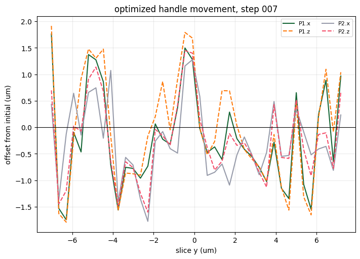
step=008 J=8.143623e-01 grad_norm=6.488777e-02 update_norm=1.076678e+00
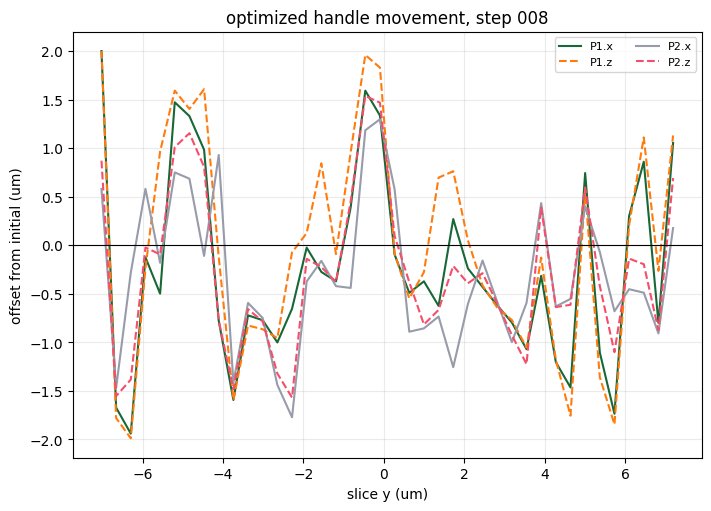
step=009 J=8.185563e-01 grad_norm=5.623399e-02 update_norm=9.530475e-01
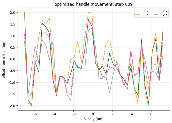
step=010 J=8.261274e-01 grad_norm=4.882751e-02 update_norm=8.121795e-01
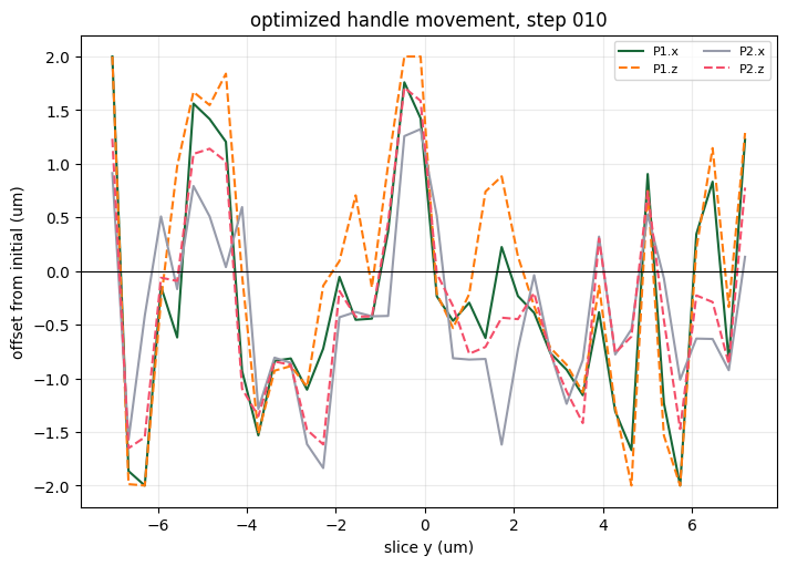
step=011 J=8.278751e-01 grad_norm=4.792816e-02 update_norm=7.551828e-01
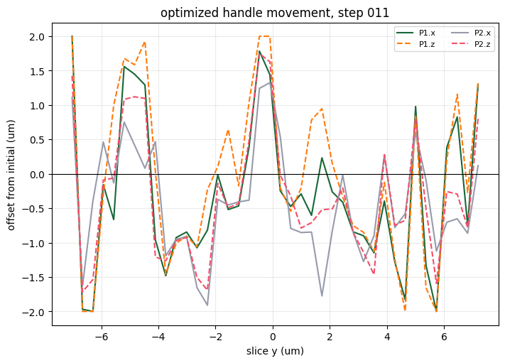
step=012 J=8.303960e-01 grad_norm=4.808631e-02 update_norm=7.320287e-01
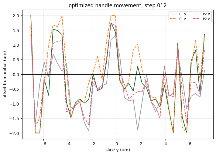
step=013 J=8.352393e-01 grad_norm=4.555706e-02 update_norm=7.102180e-01
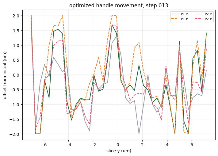
step=014 J=8.404555e-01 grad_norm=4.234298e-02 update_norm=6.518955e-01
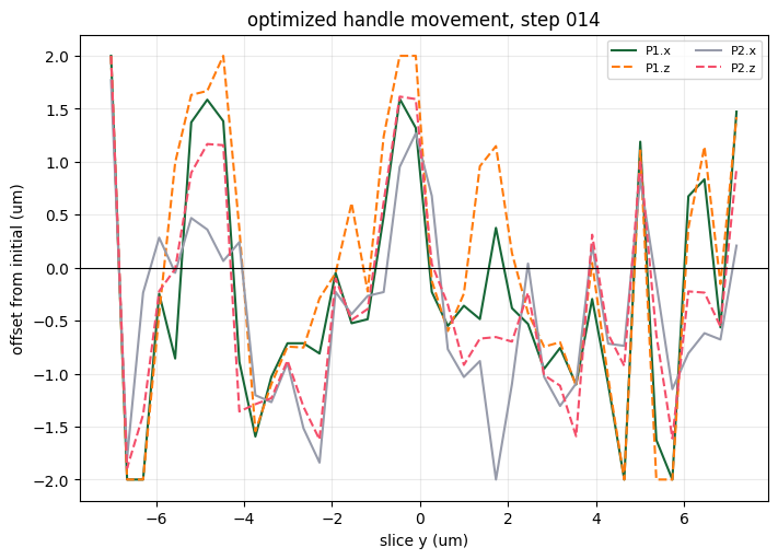
step=015 J=8.421386e-01 grad_norm=4.424526e-02 update_norm=6.083657e-01
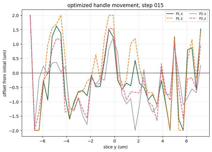
step=016 J=8.446562e-01 grad_norm=3.934184e-02 update_norm=6.159215e-01
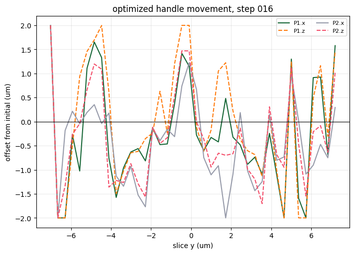
step=017 J=8.488030e-01 grad_norm=3.653978e-02 update_norm=6.527326e-01
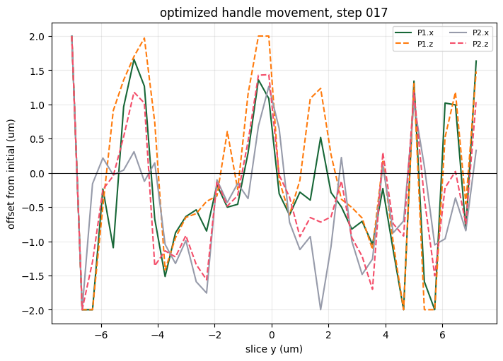
step=018 J=8.518789e-01 grad_norm=3.210772e-02 update_norm=6.475334e-01
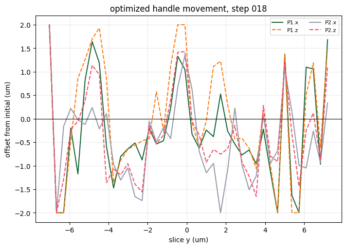
step=019 J=8.508792e-01 grad_norm=3.935945e-02 update_norm=6.372092e-01
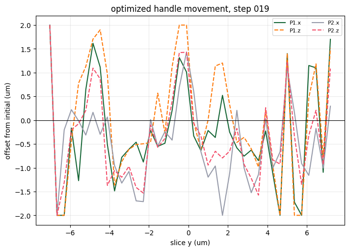
step=020 J=8.532414e-01 grad_norm=3.974937e-02 update_norm=6.747655e-01
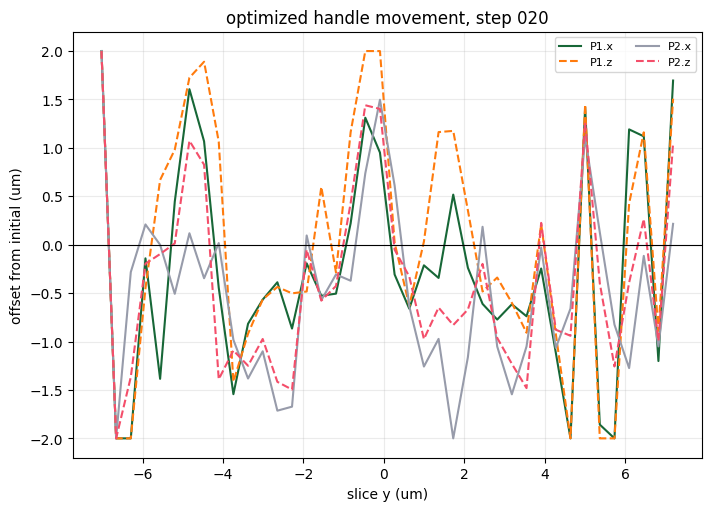
step=021 J=8.584280e-01 grad_norm=2.887912e-02 update_norm=6.105086e-01
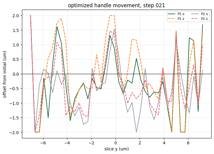
step=022 J=8.601422e-01 grad_norm=2.357042e-02 update_norm=5.054447e-01
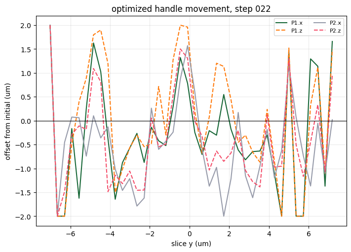
step=023 J=8.602910e-01 grad_norm=2.851601e-02 update_norm=4.868814e-01
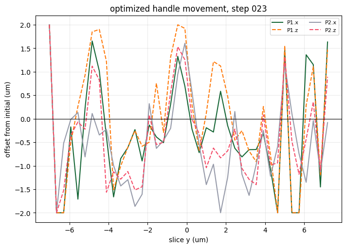
step=024 J=8.623239e-01 grad_norm=2.554610e-02 update_norm=5.018164e-01
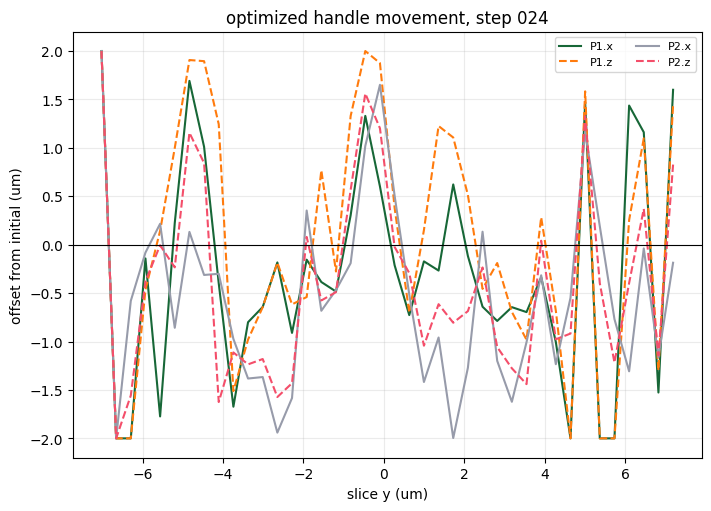
step=025 J=8.646541e-01 grad_norm=2.551006e-02 update_norm=5.174629e-01
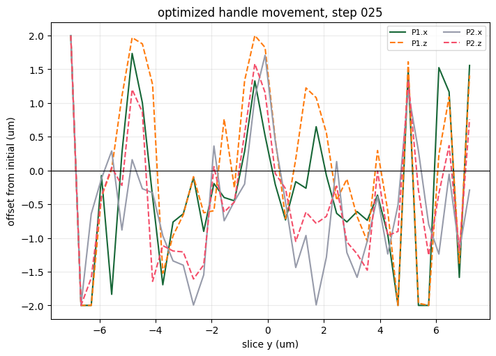
step=026 J=8.673531e-01 grad_norm=2.289925e-02 update_norm=5.282754e-01
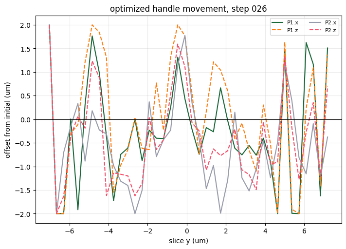
step=027 J=8.692616e-01 grad_norm=2.329600e-02 update_norm=5.107489e-01
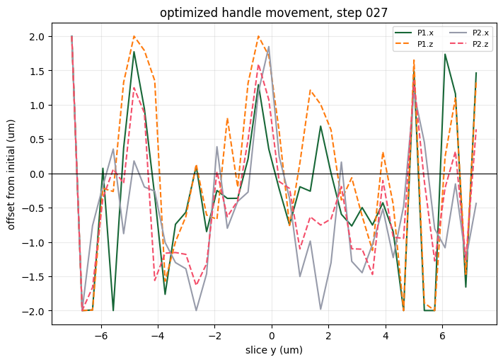
step=028 J=8.700733e-01 grad_norm=2.251716e-02 update_norm=4.864650e-01
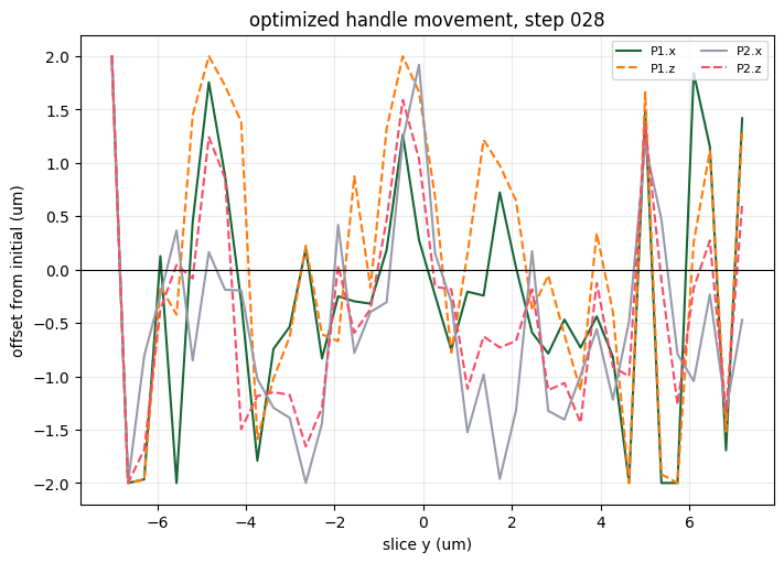
step=029 J=8.698563e-01 grad_norm=2.229957e-02 update_norm=4.683800e-01
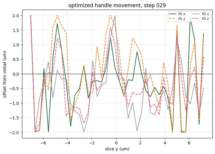
step=030 J=8.700823e-01 grad_norm=2.677319e-02 update_norm=4.726068e-01
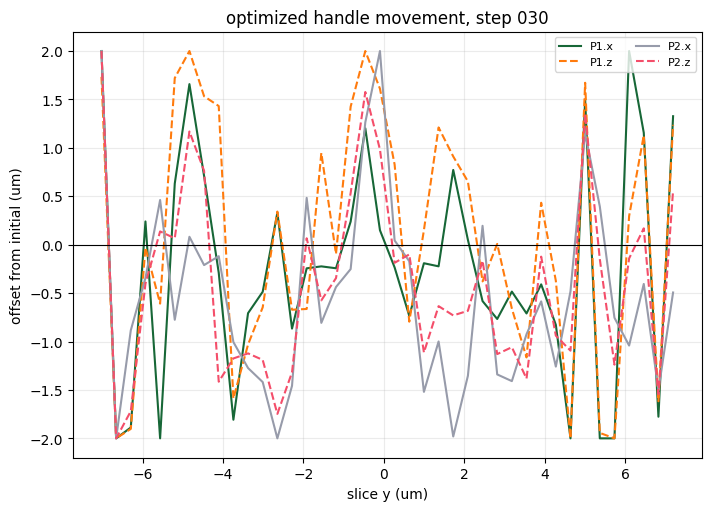
step=031 J=8.723386e-01 grad_norm=1.464958e-02 update_norm=4.727924e-01
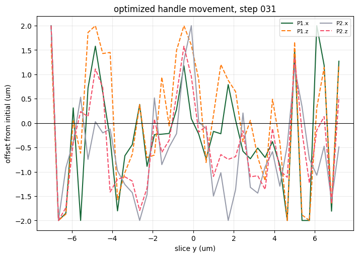
step=032 J=8.724956e-01 grad_norm=2.333174e-02 update_norm=4.261622e-01
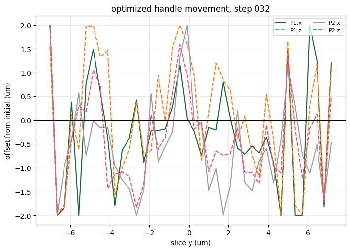
step=033 J=8.729200e-01 grad_norm=2.092927e-02 update_norm=4.017623e-01
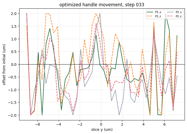
step=034 J=8.738545e-01 grad_norm=2.026383e-02 update_norm=4.145424e-01
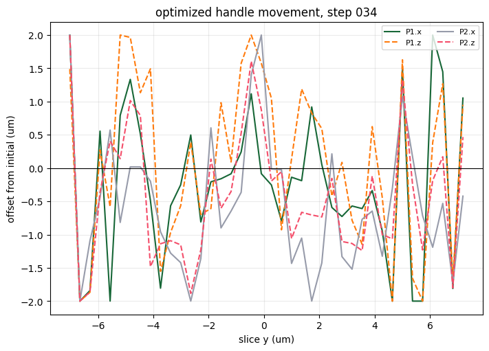
step=035 J=8.750120e-01 grad_norm=1.814470e-02 update_norm=4.417543e-01
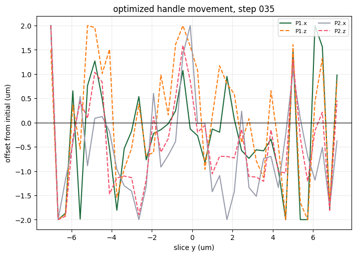
step=036 J=8.756593e-01 grad_norm=1.672866e-02 update_norm=4.490330e-01
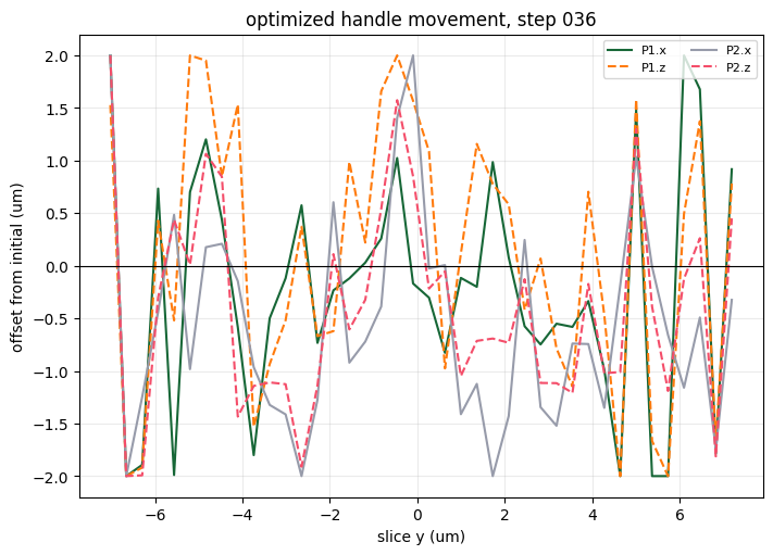
step=037 J=8.762920e-01 grad_norm=2.003075e-02 update_norm=4.662804e-01
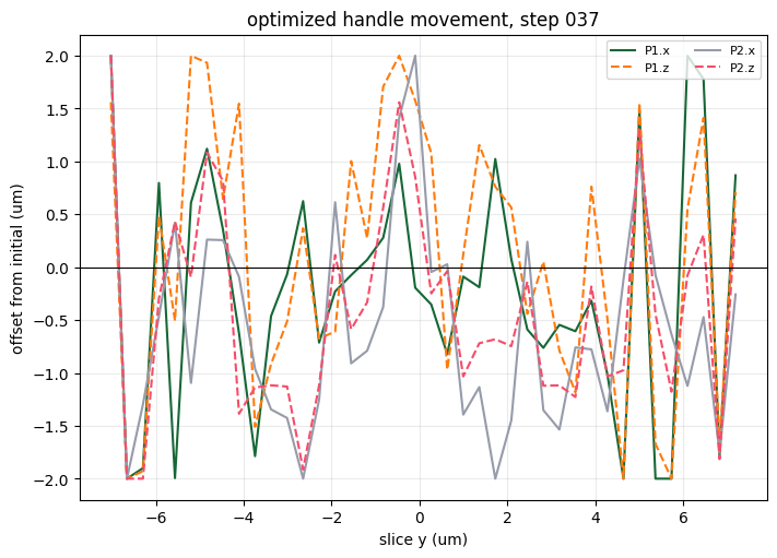
step=038 J=8.778039e-01 grad_norm=1.261456e-02 update_norm=4.981574e-01
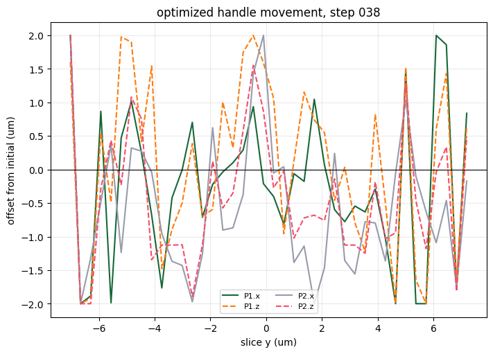
step=039 J=8.788744e-01 grad_norm=1.858660e-02 update_norm=5.416664e-01
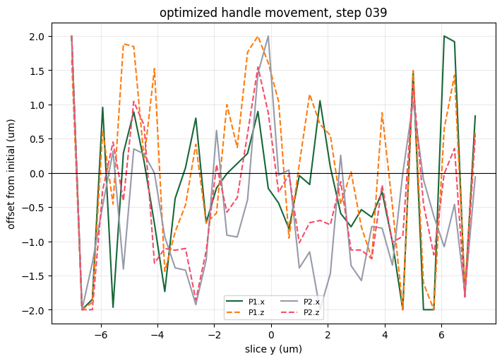
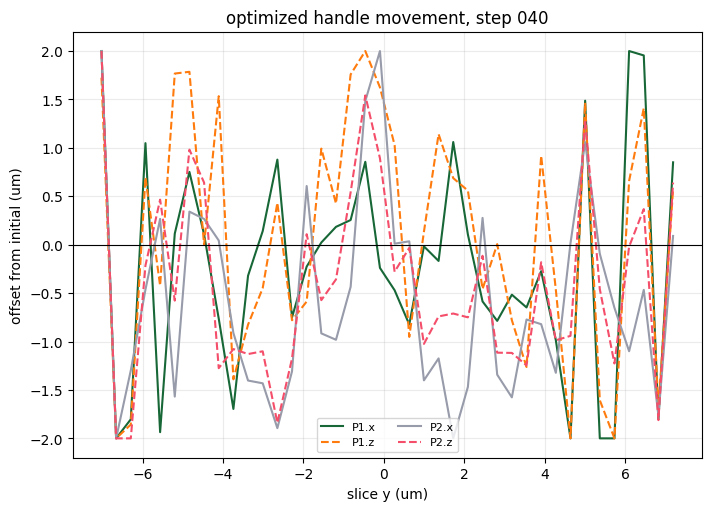
step=040 J=8.805403e-01 grad_norm=1.574789e-02 update_norm=5.477061e-01
Session 1: Export Optimized Reflector STL
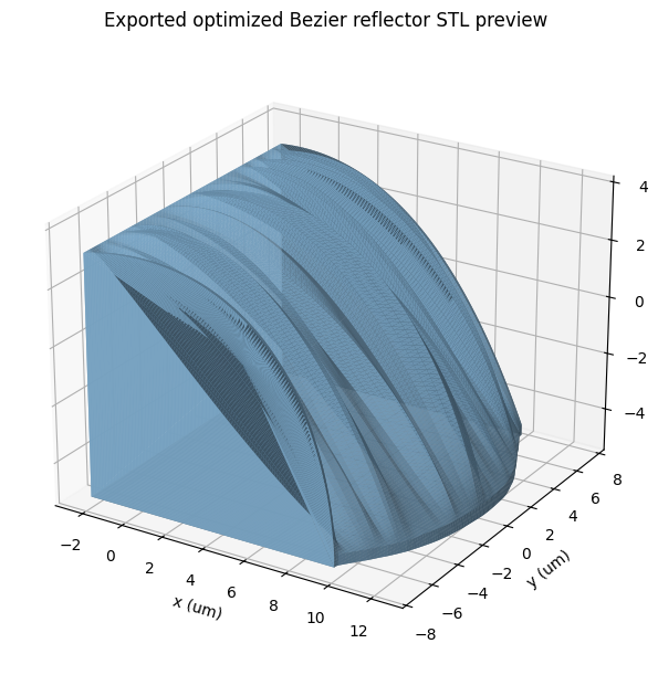
Run this after the optimization or resume-optimization cells. It uses the latest p_history[-1] when available, writes a step-labeled STL, updates results/optimized_reflector_bezier_latest.stl, and saves results/optimized_reflector_bezier_latest_p.npy. This section does not submit a Tidy3D simulation.
# Export the latest optimized Bezier reflector as one lofted STL mesh.
# The source STL is read as meters and converted to um by multiplying by 1e6.
# For consistency, this exporter writes meter-scale STL coordinates by default.
EXPORT_OPTIMIZED_STL = True
EXPORT_STL_NUM_Y_SAMPLES = 120
EXPORT_STL_NUM_CURVE_POINTS = 120
EXPORT_STL_IN_METERS = True
EXPORT_STL_PREVIEW = True


def latest_design_parameter_vector(default_p=p0):
    if 'p_history' in globals() and len(p_history) > 0:
        return np.asarray(p_history[-1], dtype=float), len(p_history) - 1, 'p_history'
    if 'p' in globals():
        return np.asarray(p, dtype=float), None, 'p'
    return np.asarray(default_p, dtype=float), 0, 'p0'


def eval_cubic_bezier_np(control_points_xz, u_values):
    cp = np.asarray(control_points_xz, dtype=float)
    u = np.asarray(u_values, dtype=float)
    one_minus_u = 1.0 - u
    b0 = one_minus_u**3
    b1 = 3.0 * one_minus_u**2 * u
    b2 = 3.0 * one_minus_u * u**2
    b3 = u**3
    return b0[:, None] * cp[0] + b1[:, None] * cp[1] + b2[:, None] * cp[2] + b3[:, None] * cp[3]


def interpolate_control_points_y_np(control_points_xz, y_source_um, y_target_um):
    cp = np.asarray(control_points_xz, dtype=float)
    y_source = np.asarray(y_source_um, dtype=float)
    y_target = np.asarray(y_target_um, dtype=float)
    order = np.argsort(y_source)
    y_sorted = y_source[order]
    cp_sorted = cp[order]
    cp_interp = np.empty((len(y_target), cp.shape[1], cp.shape[2]), dtype=float)

    for point_idx in range(cp.shape[1]):
        for coord_idx in range(cp.shape[2]):
            cp_interp[:, point_idx, coord_idx] = np.interp(
                y_target,
                y_sorted,
                cp_sorted[:, point_idx, coord_idx],
                left=cp_sorted[0, point_idx, coord_idx],
                right=cp_sorted[-1, point_idx, coord_idx],
            )
    return cp_interp


def reflector_mesh_vertices_faces_from_p(
    p_design,
    num_y_samples=EXPORT_STL_NUM_Y_SAMPLES,
    num_curve_points=EXPORT_STL_NUM_CURVE_POINTS,
):
    p_design = np.asarray(clip_p_to_bounds(p_design), dtype=float)
    cp_design = np.asarray(unpack_p(p_design), dtype=float)

    y_samples = np.linspace(design_y_edges_um[0], design_y_edges_um[-1], num_y_samples)
    cp_y = interpolate_control_points_y_np(cp_design, slice_y0_um, y_samples)
    u_values = np.linspace(0.0, 1.0, num_curve_points)

    rings = []
    for y_um, cp_xz in zip(y_samples, cp_y):
        top_xz = eval_cubic_bezier_np(cp_xz, u_values)
        polygon_xz = np.vstack(
            [
                top_xz,
                [top_xz[-1, 0], z_base_um],
                [top_xz[0, 0], z_base_um],
            ]
        )
        ring_xyz = np.column_stack(
            [
                polygon_xz[:, 0],
                np.full(len(polygon_xz), y_um),
                polygon_xz[:, 1],
            ]
        )
        rings.append(ring_xyz)

    vertices_um = np.vstack(rings)
    ring_size = num_curve_points + 2
    faces = []

    for y_idx in range(num_y_samples - 1):
        ring0 = y_idx * ring_size
        ring1 = (y_idx + 1) * ring_size
        for j in range(ring_size):
            a = ring0 + j
            b = ring0 + ((j + 1) % ring_size)
            c = ring1 + ((j + 1) % ring_size)
            d = ring1 + j
            faces.append([a, b, c])
            faces.append([a, c, d])

    start_center_idx = len(vertices_um)
    start_center = vertices_um[:ring_size].mean(axis=0, keepdims=True)
    vertices_um = np.vstack([vertices_um, start_center])
    for j in range(ring_size):
        a = j
        b = (j + 1) % ring_size
        faces.append([start_center_idx, b, a])

    end_start = (num_y_samples - 1) * ring_size
    end_center_idx = len(vertices_um)
    end_center = vertices_um[end_start:end_start + ring_size].mean(axis=0, keepdims=True)
    vertices_um = np.vstack([vertices_um, end_center])
    for j in range(ring_size):
        a = end_start + j
        b = end_start + ((j + 1) % ring_size)
        faces.append([end_center_idx, a, b])

    return vertices_um, np.asarray(faces, dtype=int)


def export_reflector_stl_from_p(p_design, stl_path, export_in_meters=EXPORT_STL_IN_METERS):
    vertices_um, faces = reflector_mesh_vertices_faces_from_p(p_design)
    vertices_for_file = vertices_um * 1e-6 if export_in_meters else vertices_um
    mesh = trimesh.Trimesh(vertices=vertices_for_file, faces=faces, process=False)
    mesh.fix_normals()
    stl_path = Path(stl_path)
    stl_path.parent.mkdir(exist_ok=True)
    mesh.export(stl_path)
    return mesh, vertices_um, faces


def plot_exported_stl_preview(vertices_um, faces, preview_path):
    fig = plt.figure(figsize=(8, 6), constrained_layout=True)
    ax = fig.add_subplot(111, projection='3d')
    ax.plot_trisurf(
        vertices_um[:, 0],
        vertices_um[:, 1],
        vertices_um[:, 2],
        triangles=faces,
        color='#86b6d9',
        edgecolor='none',
        alpha=0.9,
    )
    ax.set_xlabel('x (um)')
    ax.set_ylabel('y (um)')
    ax.set_zlabel('z (um)')
    ax.set_title('Exported optimized Bezier reflector STL preview')
    ax.view_init(elev=24, azim=-58)
    fig.savefig(preview_path, dpi=180)
    plt.show()


if EXPORT_OPTIMIZED_STL:
    p_export, export_step, export_source = latest_design_parameter_vector()
    export_label = f'step_{export_step:03d}' if export_step is not None else 'current'
    export_stl_path = RESULTS_DIR / f'optimized_reflector_bezier_{export_label}.stl'
    export_mesh, export_vertices_um, export_faces = export_reflector_stl_from_p(p_export, export_stl_path)
    export_latest_stl_path = RESULTS_DIR / 'optimized_reflector_bezier_latest.stl'
    export_mesh.export(export_latest_stl_path)
    np.save(RESULTS_DIR / 'optimized_reflector_bezier_latest_p.npy', np.asarray(p_export, dtype=float))
    export_bounds_um = np.column_stack([export_vertices_um.min(axis=0), export_vertices_um.max(axis=0)])

    print(f'Exported STL: {export_stl_path}')
    print(f'Updated latest STL: {export_latest_stl_path}')
    print(f'Design vector source: {export_source}[{export_step}]' if export_step is not None else f'Design vector source: {export_source}')
    print(f'STL coordinates written in: {"meters" if EXPORT_STL_IN_METERS else "micrometers"}')
    print(f'faces: {len(export_mesh.faces)}, vertices: {len(export_mesh.vertices)}, watertight: {export_mesh.is_watertight}')
    print(
        'bounds in um: '
        f'x [{export_bounds_um[0, 0]:.4f}, {export_bounds_um[0, 1]:.4f}], '
        f'y [{export_bounds_um[1, 0]:.4f}, {export_bounds_um[1, 1]:.4f}], '
        f'z [{export_bounds_um[2, 0]:.4f}, {export_bounds_um[2, 1]:.4f}]'
    )

    if EXPORT_STL_PREVIEW:
        plot_exported_stl_preview(export_vertices_um, export_faces, RESULTS_DIR / f'optimized_reflector_bezier_{export_label}.png')
Exported STL: results/optimized_reflector_bezier_step_040.stl
Updated latest STL: results/optimized_reflector_bezier_latest.stl
Design vector source: p_history[40]
STL coordinates written in: meters
faces: 29280, vertices: 14642, watertight: True
bounds in um: x [-2.3158, 12.3950], y [-7.2043, 7.3786], z [-5.2941, 4.0130]
Session 2: Final Simulation From Imported STL
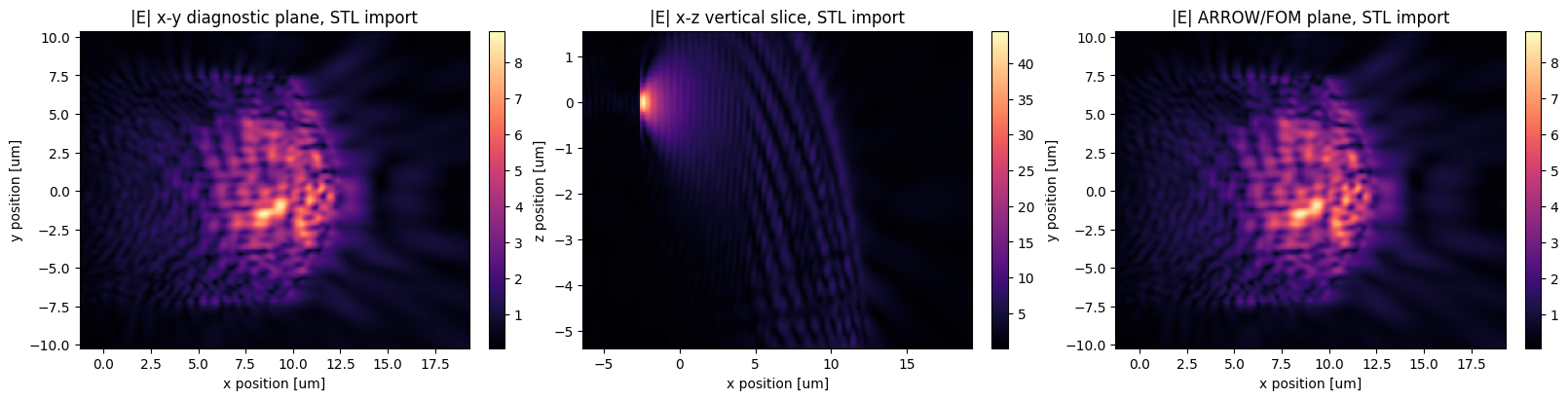
Run this after Session 1. It imports results/optimized_reflector_bezier_latest.stl into Tidy3D as a TriangleMesh, uses the same source/monitors/materials/FOM setup, submits the final simulation, and plots the imported-STL field result.
# Re-import the exported STL into Tidy3D and rerun the same diagnostic simulation.
# This checks whether the one-piece STL representation gives the same FOM/fields
# as the direct Bezier PolySlab representation used during optimization.
RUN_STL_IMPORTED_SIMULATION = True
STL_IMPORTED_INCLUDE_DIAGNOSTICS = True
STL_IMPORTED_TASK_NAME = 'bezier_reflector_arrow_imported_stl'
STL_IMPORTED_RESULT_PATH = RESULTS_DIR / f'{STL_IMPORTED_TASK_NAME}.hdf5'


def find_latest_exported_reflector_stl():
    latest_path = RESULTS_DIR / 'optimized_reflector_bezier_latest.stl'
    if latest_path.exists():
        return latest_path
    candidates = sorted(RESULTS_DIR.glob('optimized_reflector_bezier_step_*.stl'))
    return candidates[-1] if candidates else None


def stl_bounds_um_from_file(stl_path, scale_um=1e6):
    mesh = trimesh.load_mesh(stl_path, force='mesh')
    vertices_um = np.asarray(mesh.vertices, dtype=float) * scale_um
    return np.vstack([vertices_um.min(axis=0), vertices_um.max(axis=0)])


def make_reflector_structure_from_exported_stl(stl_path):
    geometry = td.TriangleMesh.from_stl(str(stl_path), scale=1e6)
    return td.Structure(
        geometry=geometry,
        medium=reflector_medium,
        background_medium=background_medium,
        name='reflector_imported_stl',
    )


def make_opt_fields_monitor_for_bounds(reflector_bounds_um):
    opt_xmin_stl = reflector_bounds_um[0, 0] - OPT_FIELDS_BUFFER_UM
    opt_xmax_stl = reflector_bounds_um[1, 0] + OPT_FIELDS_BUFFER_UM
    opt_ymin_stl = reflector_bounds_um[0, 1] - OPT_FIELDS_BUFFER_UM
    opt_ymax_stl = reflector_bounds_um[1, 1] + OPT_FIELDS_BUFFER_UM
    opt_zmin_stl = reflector_bounds_um[0, 2] - OPT_FIELDS_BUFFER_UM
    opt_zmax_stl = reflector_bounds_um[1, 2] + OPT_FIELDS_BUFFER_UM

    return td.FieldMonitor(
        name=OPT_FIELDS_MONITOR_NAME,
        center=(
            0.5 * (opt_xmin_stl + opt_xmax_stl),
            0.5 * (opt_ymin_stl + opt_ymax_stl),
            0.5 * (opt_zmin_stl + opt_zmax_stl),
        ),
        size=(opt_xmax_stl - opt_xmin_stl, opt_ymax_stl - opt_ymin_stl, opt_zmax_stl - opt_zmin_stl),
        freqs=[freq0],
        fields=E_FIELD_COMPONENTS,
        colocate=True,
    )


def make_sim_from_exported_stl(stl_path, include_diagnostics=False):
    reflector_bounds_um_stl = stl_bounds_um_from_file(stl_path, scale_um=1e6)
    stl_reflector_structure = make_reflector_structure_from_exported_stl(stl_path)
    tip_cladding_structure = make_tip_cladding_structure()
    tip_structure = make_tip_structure()

    x_min = min(reflector_bounds_um_stl[0, 0], arrow_xmin, tip_x_start_um) - pml_buffer_um
    x_max = max(reflector_bounds_um_stl[1, 0], arrow_xmax, tip_x_end_um) + pml_buffer_um
    y_min = min(reflector_bounds_um_stl[0, 1], arrow_ymin, tip_y_um - TIP_CLADDING_SIZE_UM / 2, tip_y_um - MODE_SOURCE_SIZE_Y_UM / 2) - pml_buffer_um
    y_max = max(reflector_bounds_um_stl[1, 1], arrow_ymax, tip_y_um + TIP_CLADDING_SIZE_UM / 2, tip_y_um + MODE_SOURCE_SIZE_Y_UM / 2) + pml_buffer_um
    z_min = min(reflector_bounds_um_stl[0, 2], arrow_output_z_um, tip_z_um - TIP_CLADDING_SIZE_UM / 2, tip_z_um - MODE_SOURCE_SIZE_Z_UM / 2) - pml_buffer_um
    z_max = max(reflector_bounds_um_stl[1, 2], arrow_output_z_um, tip_z_um + TIP_CLADDING_SIZE_UM / 2, tip_z_um + MODE_SOURCE_SIZE_Z_UM / 2) + pml_buffer_um

    sim_center = ((x_min + x_max) / 2, (y_min + y_max) / 2, (z_min + z_max) / 2)
    sim_size = (x_max - x_min, y_max - y_min, z_max - z_min)

    monitors = [fom_monitor]
    if include_diagnostics:
        monitors.extend([field_monitor_xy, field_monitor_xz, make_opt_fields_monitor_for_bounds(reflector_bounds_um_stl)])

    return td.Simulation(
        center=sim_center,
        size=sim_size,
        medium=background_medium,
        structures=[tip_cladding_structure, tip_structure, stl_reflector_structure],
        sources=[source],
        monitors=monitors,
        run_time=run_time_factor / freqw,
        grid_spec=td.GridSpec.auto(wavelength=lambda0_um, min_steps_per_wvl=min_steps_per_wvl),
        boundary_spec=td.BoundarySpec.all_sides(boundary=td.PML()),
    )


def _add_rect_patch(ax, x0, x1, y0, y1, color, label, linewidth=1.8, linestyle='-'):
    patch = plt.Rectangle(
        (x0, y0),
        x1 - x0,
        y1 - y0,
        fill=False,
        edgecolor=color,
        linewidth=linewidth,
        linestyle=linestyle,
        label=label,
    )
    ax.add_patch(patch)


def plot_stl_imported_simulation_setup_fallback(stl_path):
    mesh = trimesh.load_mesh(stl_path, force='mesh')
    vertices_um = np.asarray(mesh.vertices, dtype=float) * 1e6
    if len(vertices_um) > 60000:
        rng = np.random.default_rng(4)
        vertices_um = vertices_um[np.sort(rng.choice(len(vertices_um), size=60000, replace=False))]

    fig, axes = plt.subplots(1, 3, figsize=(17, 4.8), constrained_layout=True)

    axes[0].scatter(vertices_um[:, 0], vertices_um[:, 2], s=0.5, color='#1c7ed6', alpha=0.35, rasterized=True)
    _add_rect_patch(
        axes[0],
        tip_x_start_um,
        tip_x_end_um,
        tip_z_um - TIP_SIZE_UM / 2,
        tip_z_um + TIP_SIZE_UM / 2,
        '#2b8a3e',
        'SiN tip',
    )
    axes[0].axvline(source_x_um, color='#2b8a3e', linestyle='--', linewidth=1.2, label='mode source')
    axes[0].axhline(arrow_output_z_um, color='#f08c00', linestyle='--', linewidth=1.2, label='ARROW/FOM z')
    axes[0].set_title(f'STL import fallback: x-z projection')
    axes[0].set_xlabel('x (um)')
    axes[0].set_ylabel('z (um)')
    axes[0].set_aspect('equal', adjustable='box')

    axes[1].scatter(vertices_um[:, 0], vertices_um[:, 1], s=0.5, color='#1c7ed6', alpha=0.35, rasterized=True)
    _add_rect_patch(axes[1], arrow_xmin, arrow_xmax, arrow_ymin, arrow_ymax, '#f08c00', 'ARROW/FOM monitor')
    axes[1].axhline(tip_y_um, color='#2b8a3e', linestyle='--', linewidth=1.2, label='center y')
    axes[1].set_title('STL import fallback: x-y projection')
    axes[1].set_xlabel('x (um)')
    axes[1].set_ylabel('y (um)')
    axes[1].set_aspect('equal', adjustable='box')

    axes[2].scatter(vertices_um[:, 1], vertices_um[:, 2], s=0.5, color='#1c7ed6', alpha=0.35, rasterized=True)
    _add_rect_patch(
        axes[2],
        tip_y_um - TIP_SIZE_UM / 2,
        tip_y_um + TIP_SIZE_UM / 2,
        tip_z_um - TIP_SIZE_UM / 2,
        tip_z_um + TIP_SIZE_UM / 2,
        '#2b8a3e',
        'SiN tip/source aperture',
    )
    axes[2].axhline(arrow_output_z_um, color='#f08c00', linestyle='--', linewidth=1.2, label='ARROW/FOM z')
    axes[2].set_title('STL import fallback: y-z projection')
    axes[2].set_xlabel('y (um)')
    axes[2].set_ylabel('z (um)')
    axes[2].set_aspect('equal', adjustable='box')

    for ax in axes:
        ax.grid(True, alpha=0.25)
        ax.legend(loc='best', fontsize=8)

    fig.savefig(RESULTS_DIR / 'stl_imported_simulation_setup.png', dpi=180)
    plt.show()


def plot_stl_imported_simulation_setup(sim_stl, stl_path=None):
    # td.TriangleMesh.plot_eps() requires the optional networkx package, so skip it
    # entirely and use the lightweight STL point-cloud projection plot instead.
    plot_stl_imported_simulation_setup_fallback(stl_path)


def plot_stl_imported_field_results(sim_data_stl):
    field_xy_e = electric_field_magnitude_dataarray(sim_data_stl, 'field_xy', dims_order=('x', 'y'))
    field_xz_e = electric_field_magnitude_dataarray(sim_data_stl, 'field_xz', dims_order=('x', 'z'))
    fom_e = electric_field_magnitude_dataarray(sim_data_stl, FOM_MONITOR_NAME, dims_order=('x', 'y'))

    fig, axes = plt.subplots(1, 3, figsize=(16, 4), constrained_layout=True)
    field_xy_e.T.plot(ax=axes[0], cmap='magma')
    axes[0].set_title('|E| x-y diagnostic plane, STL import')
    field_xz_e.T.plot(ax=axes[1], cmap='magma')
    axes[1].set_title('|E| x-z vertical slice, STL import')
    fom_e.T.plot(ax=axes[2], cmap='magma')
    axes[2].set_title('|E| ARROW/FOM plane, STL import')
    fig.savefig(RESULTS_DIR / 'stl_imported_field_results.png', dpi=180)
    plt.show()


if RUN_STL_IMPORTED_SIMULATION:
    stl_import_path = find_latest_exported_reflector_stl()
    if stl_import_path is None:
        p_export, _, _ = latest_design_parameter_vector()
        stl_import_path = RESULTS_DIR / 'optimized_reflector_bezier_current.stl'
        export_reflector_stl_from_p(p_export, stl_import_path)

    print(f'Using imported reflector STL: {stl_import_path}')
    print(f'Imported STL bounds in um:\n{stl_bounds_um_from_file(stl_import_path, scale_um=1e6)}')
    sim_stl_imported = make_sim_from_exported_stl(stl_import_path, include_diagnostics=STL_IMPORTED_INCLUDE_DIAGNOSTICS)
    print(f'STL-imported simulation size: {sim_stl_imported.size}')
    print(f'STL-imported structures: {len(sim_stl_imported.structures)}')
    print(f'STL-imported monitors: {[mnt.name for mnt in sim_stl_imported.monitors]}')
    plot_stl_imported_simulation_setup(sim_stl_imported, stl_import_path)

    sim_data_stl_imported = web.run(
        sim_stl_imported,
        task_name=STL_IMPORTED_TASK_NAME,
        path=str(STL_IMPORTED_RESULT_PATH),
        verbose=True,
    )
    stl_imported_match = measure_arrow_profile_match(sim_data_stl_imported)
    print(f'STL-imported scalar ARROW profile match: {float(stl_imported_match):.6f}')
    if STL_IMPORTED_INCLUDE_DIAGNOSTICS:
        plot_stl_imported_field_results(sim_data_stl_imported)
else:
    print('Set RUN_STL_IMPORTED_SIMULATION = True to run the STL-imported simulation.')
Using imported reflector STL: results/optimized_reflector_bezier_latest.stl
Imported STL bounds in um:
[[-2.31577519 -7.20426942 -5.29409726]
 [12.39499579  7.37864411  4.01303441]]
STL-imported simulation size: (27.90849620382303, 22.785442025318076, 11.757131671343814)
STL-imported structures: 3
STL-imported monitors: ['arrow_match', 'field_xy', 'field_xz', 'opt_fields']
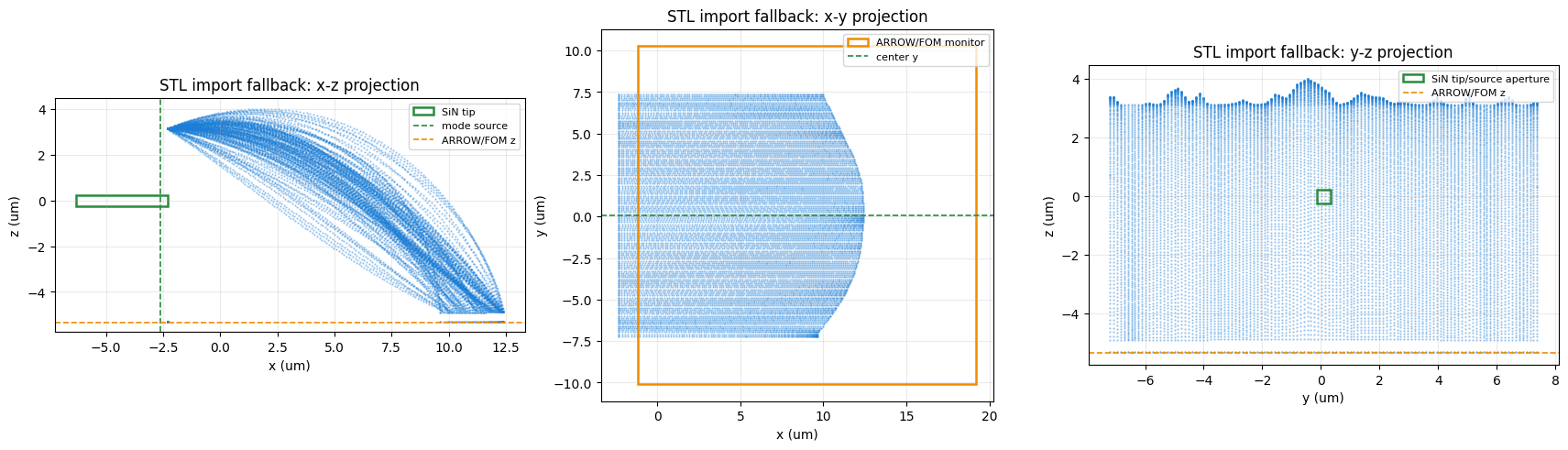
19:43:26 EDT Created task 'bezier_reflector_arrow_imported_stl' with resource_id
             'fdve-031c0998-cf19-4100-8709-892447c7a0d6' and task_type 'FDTD'.
             View task using web UI at
             'https://tidy3d.simulation.cloud/workbench?taskId=fdve-031c0998-cf1
             9-4100-8709-892447c7a0d6'.
Task folder: 'default'.
Output()
19:43:28 EDT Estimated FlexCredit cost: 0.467. Minimum cost depends on task
             execution details. Use 'web.real_cost(task_id)' to get the billed
             FlexCredit cost after a simulation run.
19:43:29 EDT status = queued
             To cancel the simulation, use 'web.abort(task_id)' or
             'web.delete(task_id)' or abort/delete the task in the web UI.
             Terminating the Python script will not stop the job running on the
             cloud.
Output()
19:43:38 EDT status = preprocess
19:43:45 EDT starting up solver
running solver
Output()
19:45:38 EDT early shutoff detected at 33%, exiting.
19:45:39 EDT status = postprocess
Output()
19:45:50 EDT status = success
19:45:52 EDT View simulation result at
             'https://tidy3d.simulation.cloud/workbench?taskId=fdve-031c0998-cf1
             9-4100-8709-892447c7a0d6'.
Output()
19:46:04 EDT Loading results from
             results/bezier_reflector_arrow_imported_stl.hdf5
STL-imported scalar ARROW profile match: 0.832700
Optional: Direct Bezier Final Diagnostic
This older diagnostic runs the final simulation directly from the Bezier PolySlab structures. Keep it off unless you want to compare the direct Bezier geometry against the imported STL geometry.
RUN_FINAL_DIAGNOSTIC = True

if RUN_FINAL_DIAGNOSTIC:
    p_final = p_history[-1]
    cp_final = unpack_p(p_final)
    plot_single_slice_bounds(control_points_xz=cp_final, title_prefix="Final")

    sim_final = make_sim(p_final, include_diagnostics=True)
    sim_data_final = web.run(
        sim_final,
        task_name="bezier_reflector_arrow_final",
        path=str(RESULTS_DIR / "bezier_reflector_arrow_final.hdf5"),
        verbose=False,
    )
    final_match = measure_arrow_profile_match(sim_data_final)
    print(f"Final scalar ARROW profile match: {float(final_match):.6f}")

    if J_history:
        plt.figure(figsize=(6, 4))
        plt.plot(np.arange(1, len(J_history) + 1), J_history, "o-")
        plt.xlabel("iteration")
        plt.ylabel("FOM")
        plt.title("Optimization history")
        plt.show()

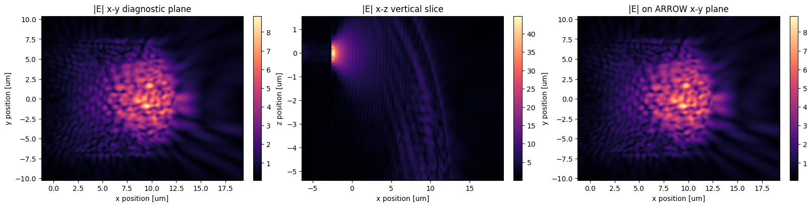
    fig, axes = plt.subplots(1, 3, figsize=(16, 4), constrained_layout=True)
    field_xy_e = electric_field_magnitude_dataarray(sim_data_final, "field_xy", dims_order=("x", "y"))
    field_xz_e = electric_field_magnitude_dataarray(sim_data_final, "field_xz", dims_order=("x", "z"))
    fom_e = electric_field_magnitude_dataarray(sim_data_final, FOM_MONITOR_NAME, dims_order=("x", "y"))

    field_xy_e.T.plot(ax=axes[0], cmap="magma")
    axes[0].set_title("|E| x-y diagnostic plane")
    field_xz_e.T.plot(ax=axes[1], cmap="magma")
    axes[1].set_title("|E| x-z vertical slice")
    fom_e.T.plot(ax=axes[2], cmap="magma")
    axes[2].set_title("|E| on ARROW x-y plane")
    plt.show()
else:
    print("Set RUN_FINAL_DIAGNOSTIC = True after optimization.")
Slice index: 20
Fixed y: 0.2695 um
Control-point status for this slice:
  P0: fixed at x -2.3158 um, z 3.1465 um
  P1: x [1.7292, 5.7292] um, z [2.0032, 6.0032] um
  P2: x [7.2543, 11.2543] um, z [-2.0561, 1.9439] um
  P3: fixed at x 12.3950 um, z -4.8714 um
Final scalar ARROW profile match: 0.881345
Points to Confirm
The framework now uses only the requested Bezier-handle parameterization:
p = [P1.x, P1.z, P2.x, P2.z] for each of 40 slices
So len(p) = 40 * 2 * 2 = 160. P0 and P3 are fixed, the 40 reflector design-slice y positions are fixed, and the bottom fill/base remains fixed. The current simulation uses the 40 Bezier PolySlab slices directly.
Current placement/material settings:
STL_Z_SHIFT_UM = -2.0
WAVEGUIDE_Z_UM = 0.0
TIP_CLADDING_SIZE_UM = 2.0
MODE_SOURCE_SIZE_Y_UM = 3.0
MODE_SOURCE_SIZE_Z_UM = 3.0
ARROW_CENTER_X_UM = 9.0
ARROW_MONITOR_GAP_UM = 0.05
TIP_SOURCE_GAP_FROM_REFLECTOR_UM = 0.30
n_air = 1.00
n_sio2 = 1.444
n_reflector = 1.60
n_tip = 2.00
E_FIELD_COMPONENTS = ("Ex", "Ey", "Ez")
SMOOTH_CONTROL_POINTS_ACROSS_Y = False
SMOOTH_ENDPOINT_LAMBDA = 1.0
SMOOTH_HANDLE_LAMBDA = 8.0
VISUALIZE_OPTIMIZATION = True
RUN_DIAGNOSTIC_FIELDS_DURING_OPTIMIZATION = False
The initial Bezier control-point trajectories are smoothed across slice y before building the reflector. The ARROW target and FOM monitor are mapped to an x-y plane underneath the reflector, normal to z. The monitor z is derived from the reflector bottom as z_base_um - ARROW_MONITOR_GAP_UM; no separate ARROW material box is used, so this output region is air background. The optimizer still updates only the 160 Bezier handle parameters.
The remaining physical choices to confirm are:
- Whether
ARROW_MONITOR_GAP_UM = 0.05 umis close enough to the reflector bottom, or should be reduced. - Whether the source gap
TIP_SOURCE_GAP_FROM_REFLECTOR_UM = 0.30 umis acceptable for representing the taper output close to the reflector while avoiding source-mode boundary warnings. - Whether
TIP_CLADDING_SIZE_UM = 2.0 umand the3.0 um x 3.0 umexpanded mode-source plane are large enough for the cladded taper-tip mode. - Whether the SiN tip index
n_tip = 2.00should be changed to another material value.



 TERMS & CONDITIONS


 How the process works:
 Try this real URL to see an example: