How to Run a Speed Sweep of an Airplane with Flow360 in 15 Minutes
In this article, we describe how to run a speed sweep of an airplane using Flow360. A speed sweep analyzes the performance of the airplane when flying at different airspeeds while carrying the same load. Such analysis is useful for determining the most fuel efficient cruise speed, the optimal climb speeds (Vx and Vy), as well as the range of the airplane. This can be done in Flow360 in 15 minutes.
We start with the model airplane created using Xfoil and Engineering Sketch Pad (ESP), Meshed using Pointwise. The generated mesh is uploaded to the Flow360 web interface.
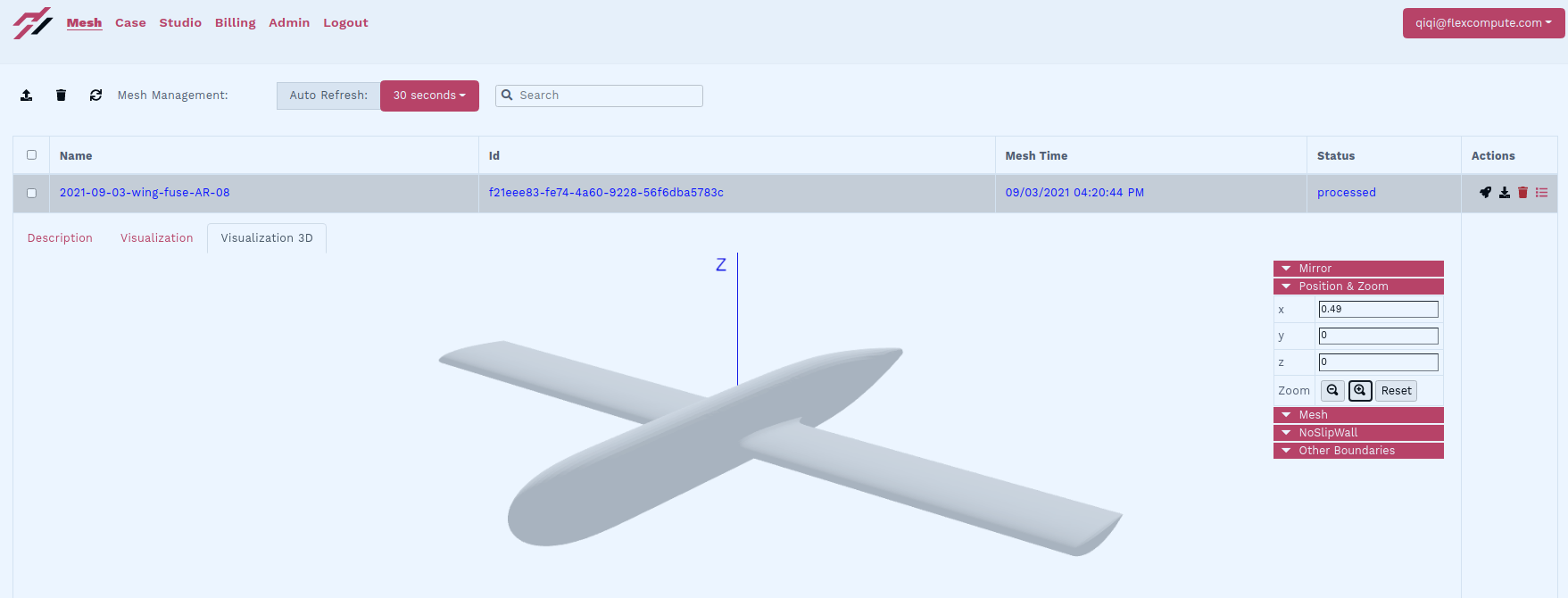
In the web interface, we fork a previous case of this mesh by clicking the “fork” button next to the case. Forking a case runs a new simulation that starts from the final solution of a previous case. This functionality is useful for continuing a previous simulation that did not have sufficient steps to converge. It is also useful for starting a new simulation with a slightly different configuration than the previous one. Forking is also used for continuing unsteady simulations.
For the speed sweep, we need to change the speed and target lift coefficient for each simulation. The speed can be modified in the “freestream”: “Mach” section of the input json file. The target lift coefficient can be found in the “runControl”: “targetCL” portion of the json input file. For a complete reference of the inputs of Flow360, please refer to our API reference at https://docs.flexcompute.com/api.html
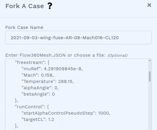
Here, we set the lowest speed at Mach 0.158 and a lift coefficient of 1.2. Note that we set “startAlphaControlPseudoStep” to 1000, which tells Flow360 to start seeking for the target lift coefficient after 1000 iterations.
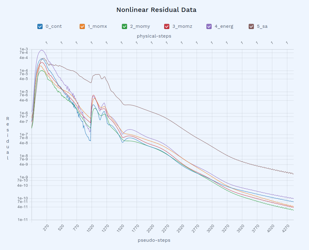
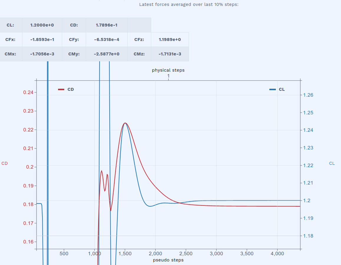
Once the case is started, the residual starts to be updated in the web interface. We observe that the convergence happens in two phases. The first phase happens within the first 1000 iterations, before Flow360 starts seeking the target lift coefficient. The second phase starts at the 1000th iteration, during which the target lift is achieved. We see that in slightly more than 4000 iterations, the target lift coefficient is achieved exactly.
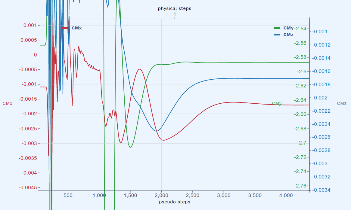
The aerodynamic moments are also updated during the simulation. Here, the x and z moments are almost exactly zero. The small values are due to the asymmetric mesh. The only significant moment is useful for determining the longitudinal stability of the airplane.
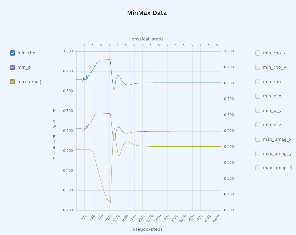
Also from the Flow360 web interface, you can examine minimum density, minimum pressure, as well as maximum velocity in the flow field, including their location. This is useful for identifying important flow features, as well as for troubleshooting diverging cases.
The speed sweep consists of a series of cases like this, at lift coefficients (CL) equal to 1.2, 1.0, 0.75, 0.5, 0.3, 0.2, and 0.1, respectively, each ensuring that the product of CL and the square of the Mach number is constant. Each of the seven cases, converging in about 4000 iterations on a mesh with 3 million nodes and 18 million cells, took about 2 minutes to complete. The entire speed sweep thus completed in slightly more than 15 minutes. After all the runs were completed, we obtain the following polar plot:
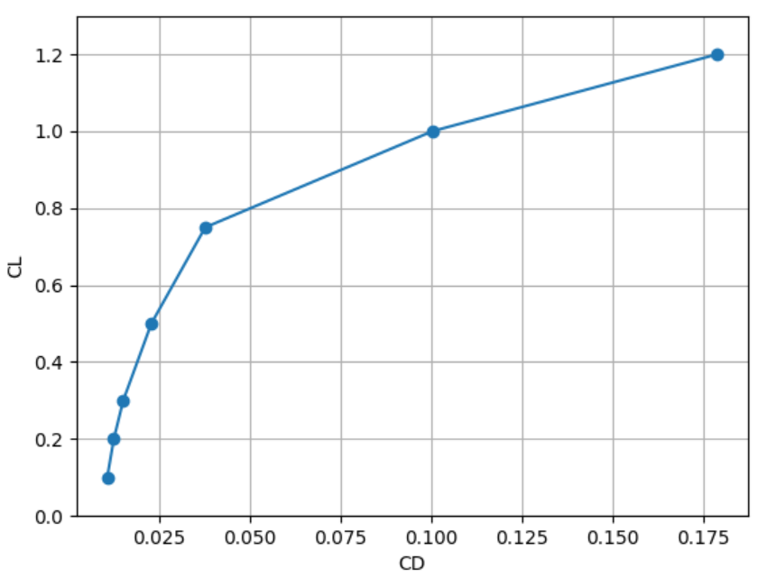
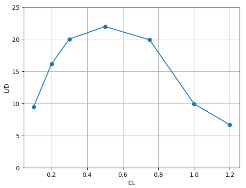
We observe that the drag coefficient increases roughly quadratically as the lift coefficient increases up to 0.75, and starts to increase significantly faster starting at a lift coefficient of 1.0. The lift to drag ratio, which determines fuel efficiency of the airplane, is also obtained. From this plot, we deduce an optimal cruising lift coefficient of 0.5, which produces the least drag for the weight of the airplane. Because drag is equal to the amount of energy required per flying distance, a lift coefficient of 0.5 means the optimal fuel economy.
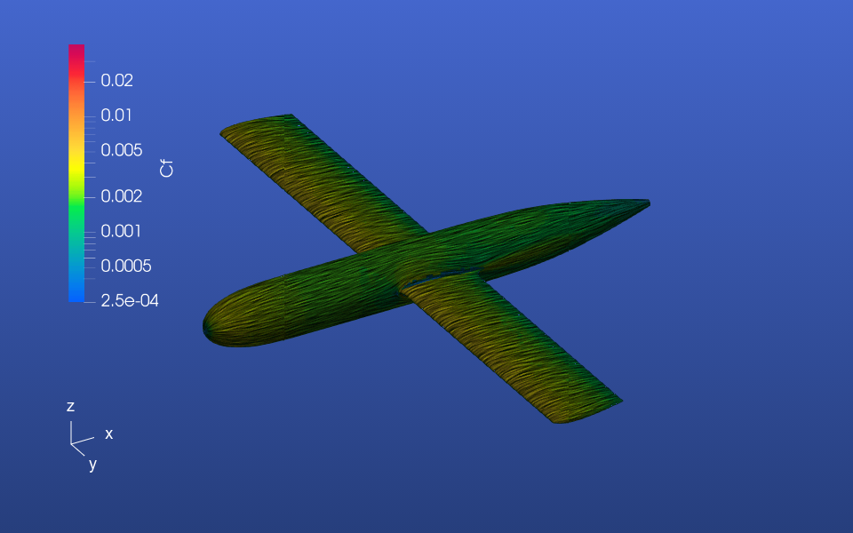
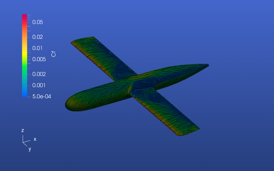
The web interface of Flow360 also visualizes the surface flow path, colored by skin friction coefficient. Here shows the case for CL=0.1
CL=0.2:

CL=0.3:

CL=0.5:

CL=0.75:
CL=1.0:
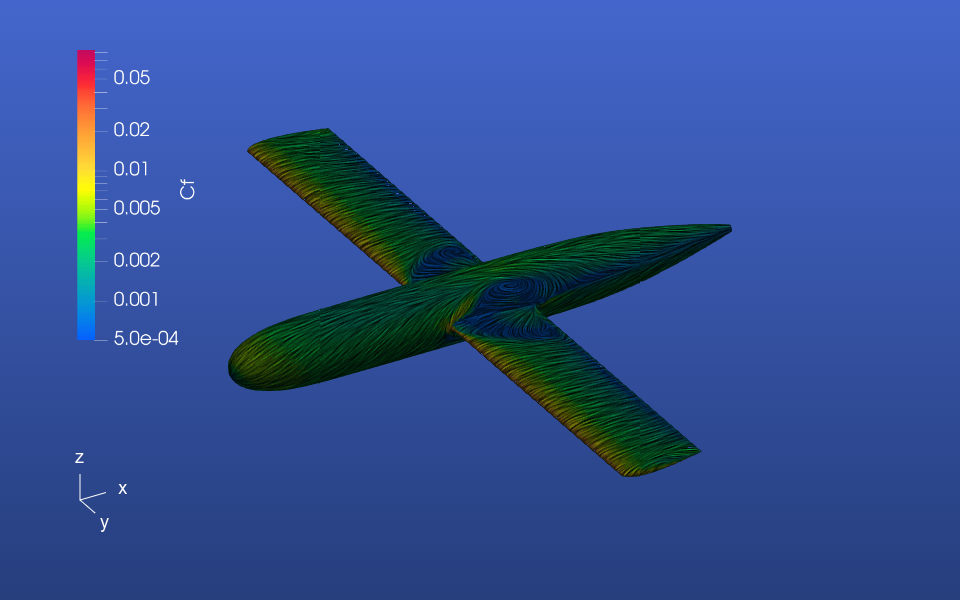
CL=1.2:
From these surface plots, we can deduce the reason for the significant drag rise starting at CL=1.0. The wing starts to stall from the root, which is typical for unswept wings or forward swept wings without significant wash-in.