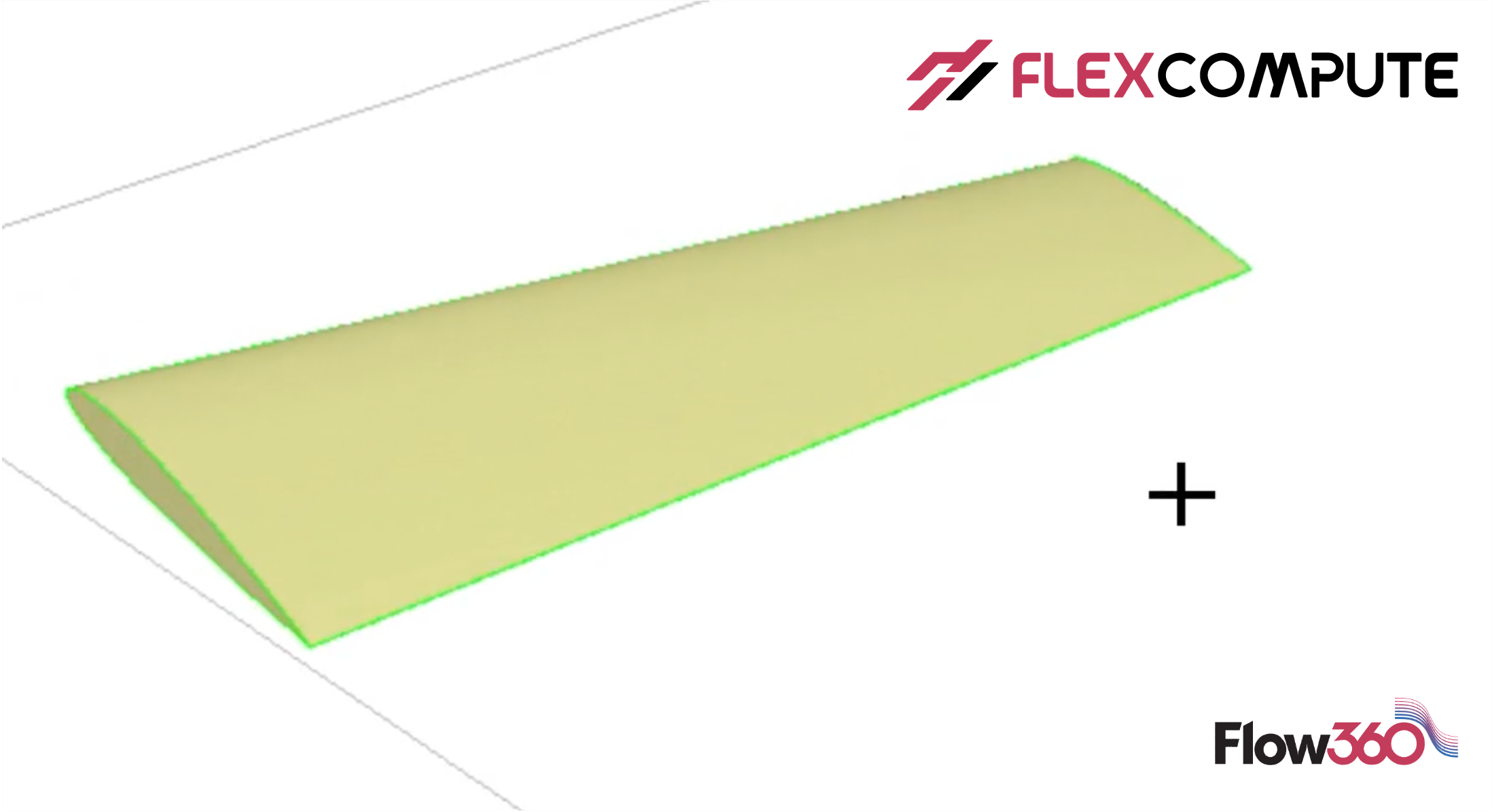
Lecture 1: How to construct an aircraft wing for CFD simulation
In this video, we will first construct the aircraft wing. We will use parameterized geometry based on Engineering Sketch Pad (ESP). The wing will be based on a set of NACA 0012 airfoil cross-sections. The basic operations in ESP, including scale, rotate and translate were demonstrated. Rule and blend commands for constructing a solid body from a set of sheet bodies were elaborated. When using the blend command, a rounded tip was also added to the wing. The edges and faces were labeled for surface meshing as well as CFD simulations.
Start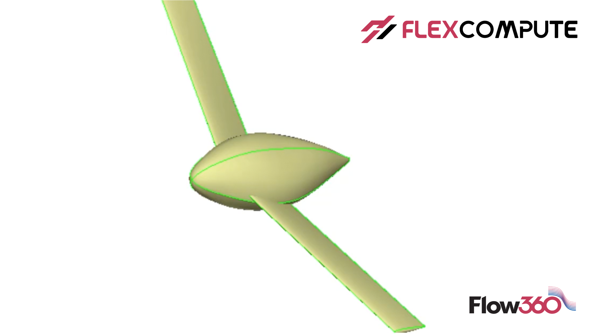
Lecture 2: How to construct the geometry of fuselage for aircraft CFD simulation
In this video, we will build a fuselage geometry. It can be constructed by blending a point and set of superellipse cross-sections. A rounded nose with customized radius was generated to demonstrate how to set up the “begList” for the blend command. Previously stored wing was restored and unioned with the fuselage to construct the full airplane geometry.
Start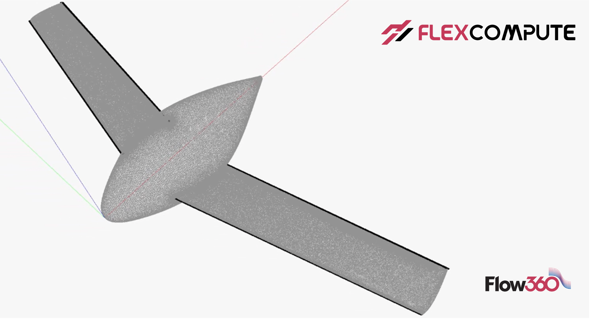
Lecture 3: How to prepare surface and volume meshes for aircraft CFD simulation
In this video, we will demonstrate how to generate the surface and volume meshes using the automated meshing workflow. When creating the surface mesh, anisotropic cells will be generated near the leading edge and trailing edges which were labeled in ESP. Once the surface mesh is generated, we will further grow a volume mesh from the surface mesh. A mesh refinement box will be added to the volume mesh to better capture the nearfield flow field.
Start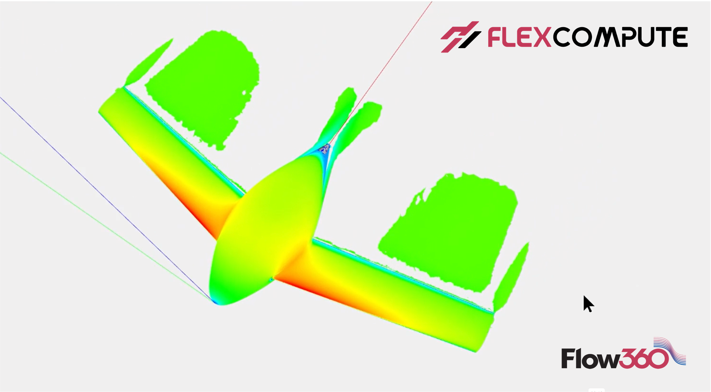
Lecture 4: How to Run a CFD Simulation in Flow360 and Visualize the Results
In this video, we will demonstrate how to set up a CFD simulation in Flow360 and check the simulation results via our WebUI. Before running the simulation, we will show how to set up the freestream condition, boundary conditions as well as other solver configurations. Once the simulation is completed, we will demonstrate how to check the convergence of residuals and examine the forces and moments acting on the airplane. Additionally, we will also show the online visualization of pressure and friction coefficients on the airplane, as well as the Q-criterion representing the vortices around the airplane.
Start
