Tiltrotor Propulsion Modeling with Blade Element Theory (Part 1 of 3)
In this series, we highlight our continued effort to study the fluid dynamics of the XV-15 tiltrotor aircraft. The full series consists of three parts: Part I provides some background on the need and utility of tiltrotor aircraft and summarizes the CFD study we carried out in 2021 using the Detached Eddy Simulation (DES) technique. Part II will discuss useful fluid dynamic propulsion approximations to model the XV-15 at a reduced computational cost. Part III will showcase the results obtained using the propulsion approximations.
##
Tiltrotor aircraft
Airplanes have led to a dramatic decrease in the time needed to travel large distances. However, they have a major drawback in that they require long runways for lifting off and landing. This limitation sparked the development of helicopters, which use rotating rotor blades to generate lift and allow vertical take-off and landing (VTOL), eliminating the need for runways. However, helicopters come with their own restrictions, including shorter ranges and slower speeds compared to airplanes.
To address these limitations, a new type of aircraft known as a tiltrotor was developed. Tiltrotors combine the hover and VTOL capabilities of helicopters with the speed and range of airplanes. As the name suggests, tiltrotors utilize tilting rotor systems that are mounted at the end of fixed wings. During vertical flight, the plane of rotation of the rotors is horizontal, generating lift in a similar way to a helicopter. As the aircraft’s speed increases, the rotors progressively tilt forward until the plane of rotation is vertical at cruising speeds. In this configuration, the rotors act as propellers, providing thrust, while the fixed wings generate lift, just like for an airplane. The result is, roughly, a doubling of the speed and range relative to a comparable helicopter, though the necessary compromises reduce hover performance and also do not provide the same cruise performance as a traditional airplane.
XV-15
Over the past decades, tiltrotor technology has gained significant attention due to the growing demand for VTOL and high flying speeds. In the late 1960s and early 1970s, a joint program was launched by the NASA Ames Research Center and Bell Helicopters to develop a tiltrotor called the XV-15 and conduct extensive flight tests. Following the XV-15 and sharing many design similarities, the V-22 Osprey first flew in 1989 and is in service in the US and Israeli military.
The blades of the XV-15 tiltrotor require a unique design to work well in both flight regimes and have high twist, solidity, and relatively small rotor radius in order to clear the body. The complexity of the tiltrotor’s geometry and the wide range of operating conditions have led to numerous experimental investigations of the XV-15’s rotor performance over the years. These experiments have been conducted in wind tunnels, including the 80-by-120ft facility at NASA Ames, as well as in-flight, and they have covered various aspects of tiltrotor performance, including hover and forward flight.
CFD for the XV-15
Advances in computer hardware and numerical algorithms have made computational fluid dynamics (CFD) a powerful tool for predicting rotor performance. There have been numerous efforts to improve the accuracy of CFD simulations of tiltrotors by developing various numerical methods.
In 2021, we set out to test the accuracy and performance of our Flow360 solver by carrying out a comprehensive numerical studyusing the high-fidelity Detached Eddy Simulation (DES) approach. We modeled the hover and propulsive/descending forward flight helicopter mode and airplane mode of a full-scale XV-15. We briefly summarize the approach and the results below. In the later parts of this article series, we will document our more recent effort to model the XV-15 using non eddy resolving CFD approaches; the motivation is to reduce the computing cost in industry, while allowing CFD solutions for the entire vehicle over a large body of flight conditions.
Multi domain CFD mesh
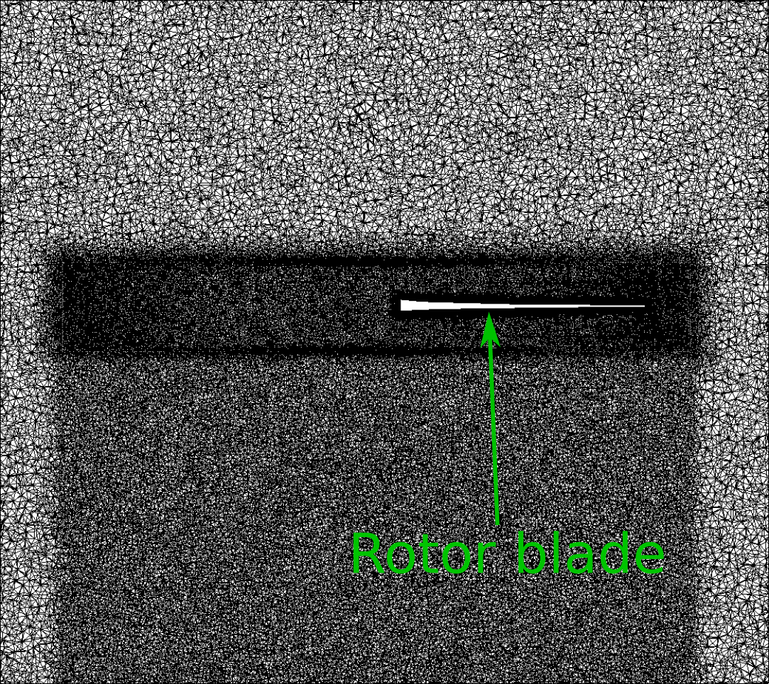
The XV-15 rotor is made up of three individual rotor blades, each consisting of five NACA 6-series aerofoil sections. To accurately capture the behavior of the air flow around the blades and, later, around the full aircraft, a multiblock unstructured meshing approach was adopted. For the rotor-only simulations presented here, the entire domain was split into two blocks: a Farfield block acting as the stationary domain and a Nearfield block acting as the rotational domain, containing the three rotor blades. This allows highly accurate body-fitted grids. The rotor hub is omitted.
The overall mesh consisted of a mixture of hexahedral, tetrahedral, prismatic and pyramidal cells to achieve the optimum balance between resolution and computational time. The mesh was further refined in particularly complex areas such as the viscous boundary layer near the blades which involved over 40 layers of hexahedral cells. A view of the mesh surrounding the rotor blade region is shown in Figure 1. The regions with higher grid resolution appear darker.

Figure 1: A section of the computational grid used in the study.
We used these carefully crafted mesh designs and the DES approach with the Spalart–Allmaras (SA) turbulence model to simulate the flow physics. In DES, the blades are treated by quasi-steady conventional turbulence modeling, while the tip vortices are unsteady, three-dimensional, and possibly chaotic which requires the Large-Eddy Simulation (LES) capability within DES. A range of results were analyzed including overall and sectional blade loads, surface pressure coefficient, skin friction and the flow field details. To validate the accuracy of the Flow360 solver, these results were compared with either previous CFD studies or experimental data from full-scale NASA wind tunnel tests. We showcase some of these results below.
Results
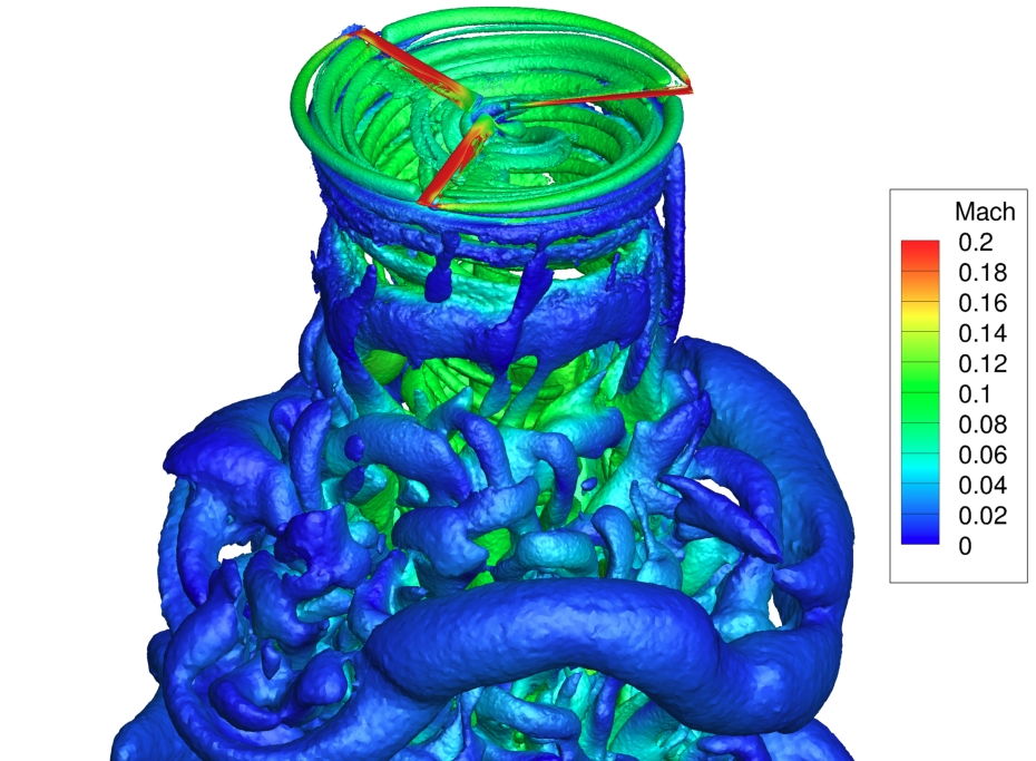
A representative flow structure appearing in the simulation is shown in Figure 3. The interaction between a blade and the tip vortex from the preceding blade is clearly visible; this is a defining feature of hover flight. The starting vortex “donut” due to the impulsive beginning of the simulation is seen about two diameters down, and is gradually moving away from the rotor. The flow field close to the rotor is nearly steady in its rotating reference frame, but the vortex system then becomes more irregular, and with current computing resources we are not in a position to assert how far down the helical vortices will persist for very large times.

Figure 2: Wake visualization of the hovering XV-15 blades using Q-criterion shaded by contours of Mach number.
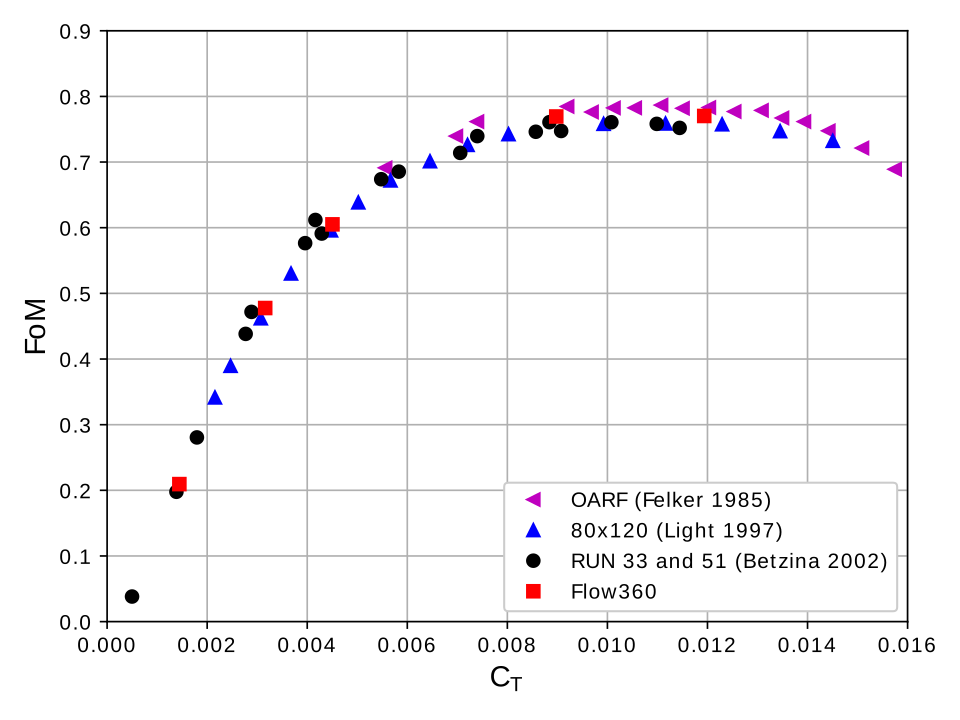
In order to benchmark the Flow360 results, we compared some important quantities with the available data. The figure of merit (FoM), defined as a ratio of ideal induced power to total consumed power is plotted versus thrust coefficient (CT) for hovering flight of helicopter mode in Figure 3. Our simulation results wereare compared with three sets of experimental data. It is clear that the results from Flow360 present a good agreement with the experimental data over a wide range.

Figure 3: Variation of the figure of merit versus the thrust coefficient.
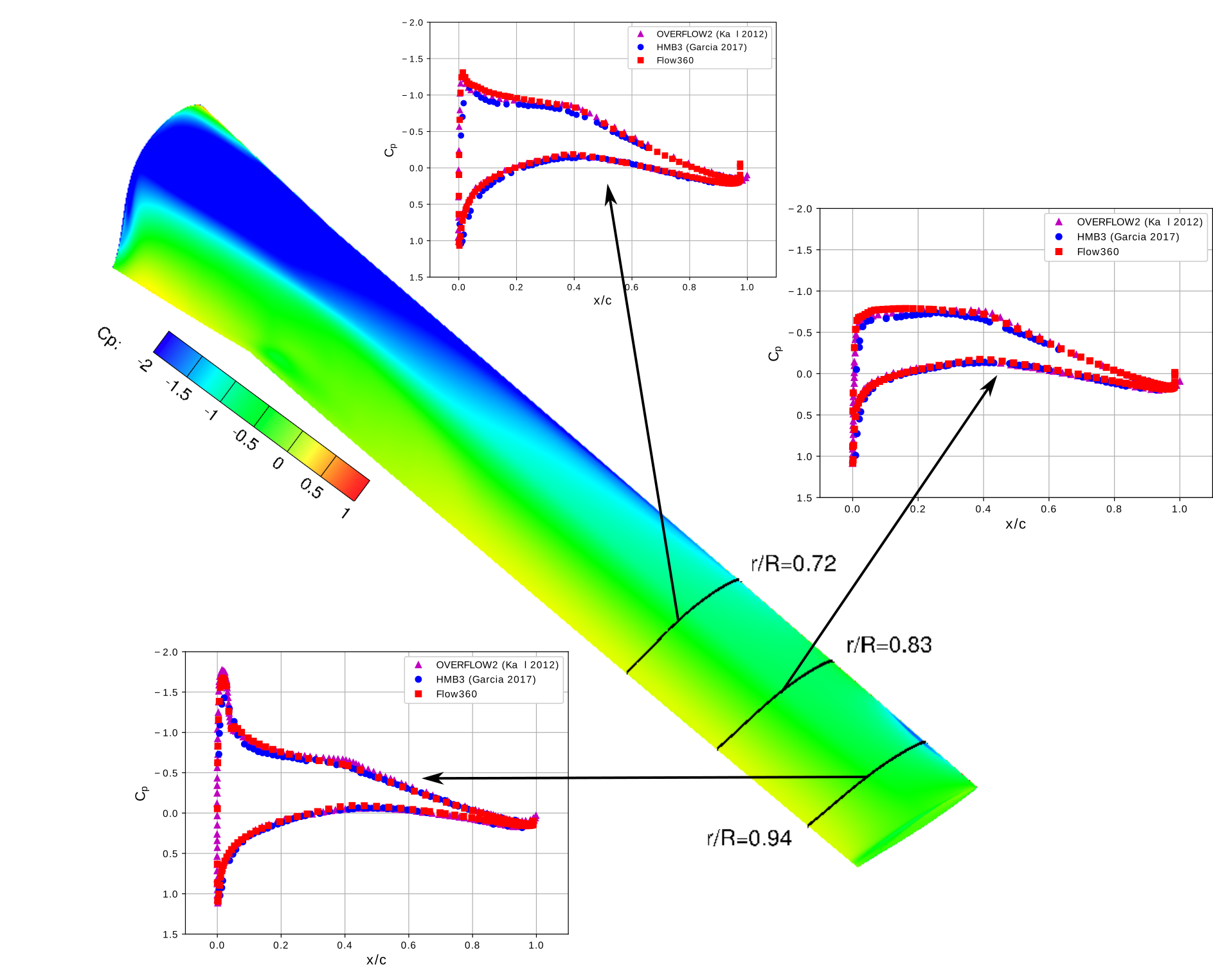
To validate the predictive capabilities of Flow360 in capturing more detailed physics, the surface pressure distribution of the blades in hovering flight was also investigated. With no experimental data available, previous CFD studies using OVERFLOW2 and HMB3 codes were used for comparison.
Three radial locations were selected for the collective pitch angle of 10° and the surface pressure coefficient (CP) was calculated based on the local rotating velocity at each radial location. In all three cases, the results from Flow360 align closely with the OVERFLOW2 and HMB3 results. The low-pressure peak at r/R=0.94 is most likely due to the blade-vortex interaction seen in Figure 2, and appears to be captured well.

Figure 4: Predicted surface pressure coefficient (CP) at a collective pitch angle of 10°.
Conclusion
Overall, after a thorough analysis and comparison with experimental data and previous CFD studies, Flow360 was proven to accurately predict the performance of the rotor blades in hovering flight of helicopter mode, as well as in airplane mode which was not discussed here. This establishes Flow360 as a reliable solver for the Detached Eddy Simulation modeling framework, with the gridding strategy and resolution used in this study. Therefore, it has a strong potential for simulations that include the wing, body, and other components.
This concludes Part I of the series. In the next article we will discuss important propulsion approximations which are useful for modeling an XV-15 like rotor systems at a much reduced computational cost.
If you’d like to learn more about CFD simulations, how to optimize them, or how to reduce your simulation time from weeks or days to hours or minutes, stop by our website at Flexcompute.com or follow us on LinkedIn.
For the expanded version of the paper this content is derived from, click here.


