Hovering Rotor CFD with Flow360 (Part 1 of 3)
In this series of articles, we highlight our efforts to accurately model the flow physics of a hovering helicopter rotor in isolation and installed on a fuselage using the solver Flow360. In Part I, the motivation for the simulations is discussed. Part II provides details on the computational setup, including the rotor blade geometry, the Flow360 CFD solver, the treatment of turbulence, the computational grid, and the sliding interface methodology. Part III presents the simulation results, including the effect of mesh refinement and time resolution, collective sweep studies, and comparisons with experimental data and other CFD codes.
Early History and Development
Helicopters are one of the most versatile aircraft in existence, capable of hovering, vertical takeoff and landing, and flight in any direction. Nevertheless, the concept of the helicopter goes back centuries. The first recorded mention of a helicopter-like design dates back to the 4th century, when Chinese children played with bamboo flying toys that spun when a stick was rapidly twisted between their palms. The famous inventor and philosopher, Leonardo da Vinci, also imagined a helicopter like machine and drew a sketch showing a hypothetical design consisting of a spiral rotor or an “aerial screw”.
The modern helicopter, as we know it today, was developed in the 1930s and 1940s, with Igor Sikorsky being credited as the father of the modern helicopter. Sikorsky built the first practical helicopter in the United States, the VS-300, in 1939. This early design had a single main rotor and a small tail rotor to counter the yawing moment of the main rotor. Sikorsky continued to refine and improve upon his designs, culminating in the first mass-produced helicopter, the Sikorsky R-4, which was used extensively as early as World War II.
In order to design a functioning helicopter, a great deal of engineering and innovation is required. The main rotor of a helicopter is a rotating wing that generates thrust to lift the aircraft off the ground and keep it aloft. However, in order to make the conventional helicopter design functional, stable, and controllable, a tail rotor is also required. The tail rotor provides a counteracting torque to the main rotor, allowing the pilot to control the helicopter’s direction and prevent it from spinning uncontrollably. A minority of designs have counter-rotating rotors, whether in tandem, side-by-side, co-axial or intermeshing, and dispense with the tail rotor.
Additionally, the complex design of a helicopter requires a sophisticated control system to allow the pilot to manage the aircraft’s motion with six degrees of freedom. Helicopters use a combination of hydraulic, sometimes electrical, and mechanical controls to adjust the rotor blades in collective and in cyclic mode, and the tail rotor, allowing the pilot to change the helicopter’s direction and altitude. Most rotors are also articulated, initially with hinges and now often with elastic connections.
Despite the many challenges involved in designing and building helicopters and their high cost, whether initial, in maintenance or in fuel, they are widely used in a variety of fields, from military operations to emergency rescue and medical transport. Helicopters have also played a significant role in advancing scientific research and exploration, allowing researchers to access remote locations and study the natural world from new perspectives.
CFD Modeling of Hovering Rotors
Early development cycles of helicopters involved basic theories boosted by engineering judgment, followed by testing of various scale models and prototypes in wind tunnels or building working prototypes which could be tested. In the modern era, however, computer modeling has transformed the way we design and refine all aircraft. Computational modeling allows rapid performance characterization. However, despite the high degree of maturity reached by engineering-level calculations, computational fluid dynamics (CFD) codes still face challenges in accurately predicting hovering rotor performance.
CFD predictions have reached an accuracy level of within one count (0.01) in Figure of Merit (FoM). Figure of Merit is the ratio between the ideal induced power calculated from the basic theory and the actual required rotor power. Typical values in the best conditions range from 0.7 to 0.8. A higher FoM value, therefore, means lower fuel consumption and longer hover endurance, and can also mean higher max takeoff weight for a given engine power and rotor diameter.
However, some uncertainty remains about the accuracy of CFD results and the sources of contributing errors. That is, are accurate high-level results correct for the right reasons or are there compensating errors at play. In addition, a 0.5% error in FoM prediction is equivalent to the weight of a single passenger, highlighting the importance of accurate CFD prediction. Typical experimental datasets provide only a level of accuracy within 1-2 counts in FoM, indicating the need for further improvements in both computation and experiment. Engineers also deal with the FoM of the rotor being diminished by the download on the fuselage, which introduces additional difficulties; the power to drive the tail rotor is also sizable.
Hover Prediction Workshop
The Hover Prediction Workshop (HPW) has attempted to improve the accuracy and fidelity of isolated hovering rotor simulations since 2014. However, many of the issues raised in the 2017 status paper are still present in current simulations, especially for more complex problems than an isolated rotor. These issues suggest that many hover performance predictions may have good agreement with experimental data partly due to error cancellation. Only two quantities of interest are typically assessed, namely the thrust for a given RPM and blade angle, and the torque which sets the FoM. The lack of a comprehensive experimental dataset is another limitation that hinders progress in rotor-in-hover simulations. There are also “hangar effects” in testing which are difficult to model with CFD.
To address these limitations, the HPW has set a new hover focus problem, with future research planned to focus on fuselage download predictions and in-ground effect simulations of the Hover Validation and Acoustic Baseline (HVAB) rotor. While careful attempts have been made for isolated rotors in terms of grid resolution, temporal accuracy and turbulence modeling, close to no sensitivity studies exist for installed rotor predictions.
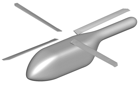
For this reason, one of the main aims of this article series is to perform rigorous mesh-refinement and time-step studies to give higher confidence in the performance predictions for both isolated and installed rotor configurations. Based on the findings from this study a collective sweep is performed for the HVAB blade. Additionally, as the HVAB blade experimental data has not yet been published, lower blade tip Mach number simulations representative of the Pressure Sensitive Paint (PSP) blade simulations are also performed. As seen in Figure 1, our CFD model is missing the rotor hub. Except for forward flight conditions when the velocities in the hub region can become substantial, we can ignore the rotor hub without greatly affecting the quality of the simulation results.
Following the earlier theme of our article series, this first part focuses on the motivation for conducting the simulations. In the second part of the series, we will provide details about the computational setup used in the study. We will present the details of the rotor blade geometry which we used for our simulations. We will also present relevant details about our CFD solver, Flow360. It is based on hardware/software co-design with emerging hardware computing, leading to unprecedented solver speed without sacrificing accuracy. We will discuss a few details about the computational grid utilized to solve such problems. For instance, we utilized the “sliding interface methodology” to simulate the motion of a rotor blade rotating around its hub; this approach helps to simulate the system more efficiently. The treatment of the tip vortices and the interaction between the rotor vortical wake and the fuselage in terms of turbulence will also be discussed.
In the last and 3rd part of the series, we will present the results obtained from our simulations. In particular, we will demonstrate the effect of changing the grid resolution on the simulation results, as well as the effect of changing the time step resolution used to resolve the movement of the rotor blades. We will then present results of a collective sweep study performed at two blade tip Mach numbers for isolated and installed rotors, and comparisons are made with experimental data and predictions from other CFD codes, where available. The Flow360 results show strong correlation with reference data and resolved high-resolution wake structures, showing the applicability of Flow360 to hovering rotor solutions.
This concludes Part I of the series. In the next article we will discuss the details of the computational model used to simulate the hovering rotor conditions.
If you’d like to learn more about CFD simulations, how to optimize them, or how to reduce your simulation time from weeks or days to hours or minutes, stop by our website or follow us on LinkedIn.
For the expanded version of the paper this content is derived from, click here.