Propeller Simulation Techniques in RANS CFD using Flow360
Flow360 can simulate a propeller using four different techniques, each with its own drawbacks and advantages. The goal of this article is to provide an introduction to each technique and give you the information needed to decide which technique is most appropriate for your simulation needs.
Four Different Propeller Simulation Techniques
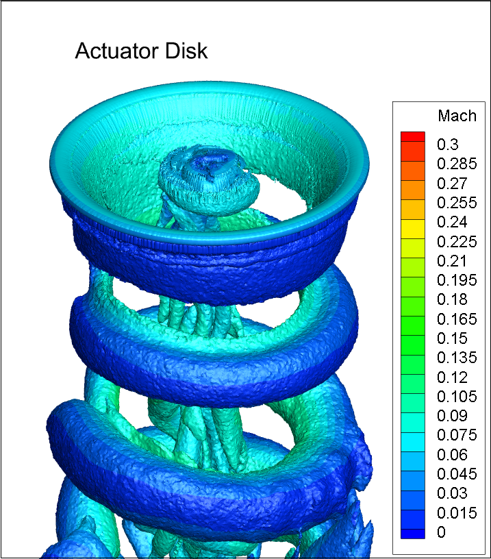
1. Actuator Disk (AD)
The Actuator Disk technique is the easiest one to use in that all you need to give Flow360 is the thrust and torque distribution for your propeller. Flow360 takes that thrust and torque distribution and uses it to locally accelerate the flow. You can then see the downstream effects of the propeller’s thrust and how it affects the performance of whatever is downstream. The drawback is that AD can only be relied on if the flow is near perpendicular to the propeller disk. The AD technique assumes a uniform distribution of thrust along the azimuth. The thrust value and thrust distribution needs to come from another CFD simulation, momentum theory, experimental data or whatever other source you choose.
2. Steady-State Blade Element Theory (BET Disk)
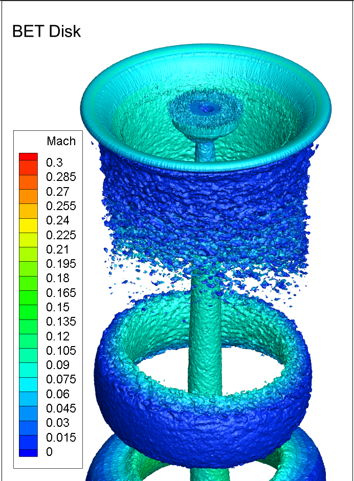
When doing a steady-state BET simulation you provide a set of 2D polars as well as some geometry information representing the performance and shape of the propeller’s blades. That is, you provide a geometrical definition (chords and twists at many stations along the span of the blade) along with the 2D polars (lift and drag) at many slices along the span. The solver then uses that information to “build” a virtual blade in the flow. At each station the solver looks at the incoming flow, the defined geometry and its performance polar to calculate the forces that the blade would exert on the fluid and it applies those forces. The biggest advantage of BET over AD is that it is still accurate when the flow is not perpendicular to the propeller disk and it does not require you to know the thrust ahead of time like AD does.
Steady-state BET represents the propeller as a disk but it doesn’t mean that the thrust will be uniform along that disk. If the inflow is asymmetric then the BET effects will also be asymmetric. However, all time-dependent phenomena (e.g., tip vortices) will be averaged out.
To learn more about how and when to use the BET Disk model please visit this case study in our Flow360 documentation page.
3. Time-Accurate Blade Element Theory (BET Line)
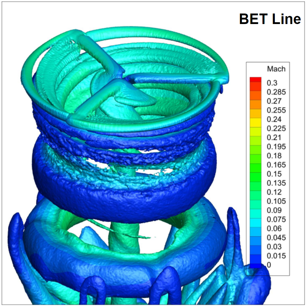
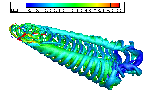
The inputs to a time-accurate BET Line simulation are mostly the same as the steady-state BET Disk above. What is different is that you will now have your virtual blades spinning around and you will capture all the time-dependent effects. This, however, comes at the cost of much larger run times because the solver needs to simulate a lot of steady-state subiterations in order to come up with a time-accurate simulation over a relevant time span. The user should have an understanding of what sort of time scales the solution needs in order to capture the details of the flow physics while doing a long enough simulation to capture downstream effects of the propeller’s wake.
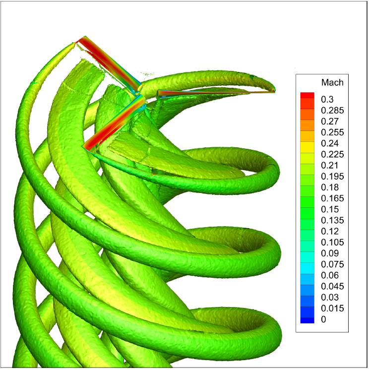
4. Time-Accurate Rotating Propeller (TARP)
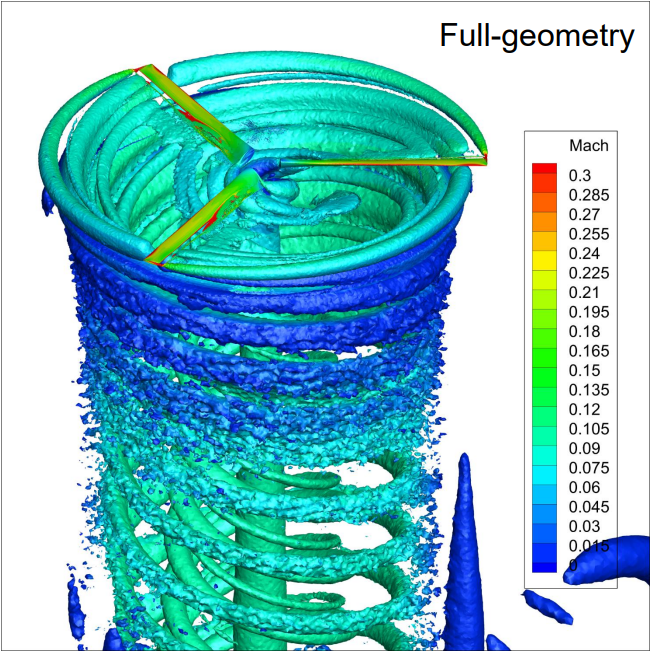
This is the most computationally expensive technique, but also the most accurate. Here, you mesh the actual propeller geometry with hub and everything else and spin the propeller within a hockey puck like sliding interface. You can model multiple propellers each within their own sliding interface. You can model a sliding interface within a sliding interface to model various things like a helicopter’s cyclical blade oscillations. You can even spin things like a whole airplane to simulate aircraft stalling spins or model dynamic flight derivatives on entire configurations.
All the important flow physics are accurately captured (with a sufficiently resolved mesh). Not only can you have great trust in the resulting forces and moments, but you can also see how the wake from the propeller moves downstream and affects the various wings/bodies/etc. that are behind the propeller.
When to use which technique?
The choice of which technique to use depends on many factors:
- Do you have CAD for your propeller?
- Do you know the propeller’s 2D sectional lift and drag polars?
- Do you know the propeller’s performance (thrust/torque)?
- What is your flowfield like?
- Do you care about the forces and moments on the propeller, or the propeller’s effect on bodies downstream of it, or both?
- How much accuracy is required?
- How much effort/time do you want to spend simulating this case?
- …
If we go in order of simplicity:
-
Steady-state AD is best suited when all you have is the expected/desired thrust and torque values. The propeller doesn’t have to exist yet, for example, all you may know is that you need a certain amount of thrust and you want to see how that thrust will affect the flow downstream. Then AD is your best option as long as the inflow is perpendicular to your propeller disk (i.e., the thrust distribution is constant around the azimuth of the disk). One thing to note here is that if you change any of the simulation parameters (RPM, inflow speed, etc.), then you will most likely need to adjust the amount of thrust and torque your virtual propeller provides and you will need to know this from some other source (experimental, lower order methods, etc.).
Since it requires propeller performance ahead of time, the AD approach is only useful for scenarios when you want to learn how the propeller affects things downstream of it.
- Steady-state BET Disk is a very common option because most of the time you will know the 2D cross-section polars of your geometry. Once you have that information then you can simulate any scenario without having to change the propeller parameters. This makes running sweeps of any condition (alpha, air speed, RPM, etc.) very simple. You also don’t need to know the propeller’s performance ahead of time. With BET Disk you get both an idea of a propeller’s performance but also how it will affect things downstream of it. This is used a lot to test various propeller designs without having to CAD up each geometry variation which is very useful in the early design stages.
- Time-accurate BET Line is a lot more computer resource intensive then steady-state BET Disk, but it gives you a lot more information about how the blades behave in time. The most common scenario is if you know that you will have important time varying effects of vortices impinging on other bodies downstream, then you need time-accurate BET Line instead of steady-state BET Disk. Time-accurate BET Line gives you everything steady-state BET Disk does plus some information as to how things vary in time.
- Time-accurate rotating propeller (TARP) is your best choice if you have the CAD geometry and you need the highest accuracy possible. It is the most complex of all four techniques, but gives you the most accurate answers possible to all of your flow physics questions.
In any event, if you are still in doubt about which technique to use or have further questions. Please do not hesitate to reach out via support@flexcompute.com and we will get back to you very quickly.
Summary Table
| Technique | Pros | Cons | When to Use | Run Times |
|---|---|---|---|---|
| AD | Quick and simple | Only get information on objects downstream of propeller Can Only simulate normal inflow conditions |
When all you have is the propeller’s thrust and torque and your flow is normal to propeller disk | Very fast 1-10 (mins) |
| BET Disk | Quick and simple Very wide range of uses |
Requires accurate information about propeller’s 2D sectional performance | Most applications when you need quick turnaround with high precision and wide range of use cases | Fast 10-20 (mins) |
| BET Line | Same as BET disk but with additional time varying information | Same as BET Disk but with much longer run times | Same at BET Disk but time varying phenomena are captured | Longer 20-100 (mins) |
| TARP | Most accurate Captures all relevant flow physics |
Requires CAD geometry and high quality mesh Very resource intensive |
When nothing but the best will do | Longest 100-200 (mins) |
[1] Rotor5: Rotor analysis under 5 hours using ultra-fast and high-fidelity CFD simulation and automatic meshing
Rotor Analysis in Under 5 Hours Using Ultra Fast and High FIdelity CFD Simulation and Automatic Meshing
