Exploring the Fluid Dynamics of an Electric Short TakeOff and Landing (eSTOL) Aircraft (Part 2 of 3)
In PART I of this series, we presented why an eSTOL aircraft is important for future urban transportation and laid the foundation for carrying out a systematic study of its fluid dynamics. Here, we will discuss several propulsion approximations which are used in this context and how we can use the Finite Volume technique to model the associated Navier-Stokes equations. Part III will showcase the results from this study and how they helped us to better understand the fluid dynamics of eSTOL aircraft.
PART II
(Approximate reading time: 10mins)
Propulsion Approximations
As we discussed in PART I, modeling the fluid dynamics of propellers is a major challenge. The rotation speed of propellers can be very high, which implies very small time scales and complex interaction among the fluid flow associated with each blade. However, many phenomena in science and engineering can be approximated with simplified mathematical representations. This allows us to model the relevant physics at a greatly reduced cost. Fortunately, decades of theoretical and experimental research has shown that the complex fluid dynamics of propellers can be approximated by several simpler propulsion models. In our study, we utilize three such models: Actuator Disk (AD), steady Blade Element Theory (BET Disk) and transient Blade Element Theory (BET Line). The fully resolved (FR) results, which simulate the time-accurate flow field affected by the actual rotor geometry, do not assume such approximations and will be treated as the reference. Below we briefly discuss the three approximations.
Also see Propeller Simulation Techniques in RANS CFD Using Flow360 for more information about these modeling approaches
In AD, the individual propeller blades are ignored and the entire rotor is modeled as an effective disk. One can imagine it as the blurry “disk” that forms when the propellers of an airplane or helicopter rotate rapidly. The actuator disk thus formed is assumed to take in fluid from the upstream side, perform mechanical work, and push out the accelerated fluid from the downstream end. Only two parameters are needed to define an AD: the axial force (or “Thrust”) directed along upstream-to-downstream sides of the propeller-motor system, and the circumferential force (or “Torque”), which is along the rotation sense of the hypothetical propellers. A major drawback of introducing such approximations in AD is that it prescribes a uniform force density around the disk, and, therefore, does not capture the physics properly if the incoming fluid is not perpendicular to the main rotor disk.
A BET Disk model is more advanced than the AD model. Although it still ignores the individual propellers and approximates the rotor as a disk, the axial and circumferential force calculations are better defined. The lift and drag coefficients defining the characteristics of a model propeller are first obtained empirically through pre-calculated lookup tables. These values can depend on the location of the point-of-interest in the propeller plane, on the local Mach and Reynolds numbers, and on the local angle of attack of the fluid. Once we have calculated the lift and the drag coefficients across the blade, we can then define an effective disk driven by these fast rotating propellers (a “steady-state” configuration). It then allows us to calculate the effective axial and circumferential forces throughout the disk. The calculations are non-trivial but still much faster and cheaper as compared to modeling the propeller blades fully.
The third model, BET Line, goes a step further than the BET Disk model. Instead of converting the propeller blade lift and drag profiles into a virtual disk, it retains their individual contributions. Therefore, as the propeller is rotated, time-accurate interaction of the forces and flow field generated by the individual blades are modeled. Unlike the first two approximations, BET Line is time-dependent and produces a tip vortex for each blade, instead of a steady vortex sheet. Furthermore, the interaction of the rotor wake with downstream components is more realistic in this case. However, as compared to the BET Disk approach, we need to spend much more computational resources to simulate the individual blades and the associated flow field.
With these approximations, we can now start modeling the system using computational fluid dynamics. As we discussed earlier, it is useful to study the important components of the aircraft separately before considering the full configuration. Therefore, we first model an isolated propeller system attached to a central motor hub. This will help us to test the efficacy of the different propulsion approximations (AD, BET Disk, BET Line) against the Fully Resolved (FR) approach.
Finite Volume
The fluid dynamics of the system is governed by the Navier-Stokes equations, which are highly non-linear partial differential equations. They require advanced computational fluid dynamics methods to solve properly. Flexcompute’s Flow360 solver employs a Finite Volume Method (FVM) to model these equations.
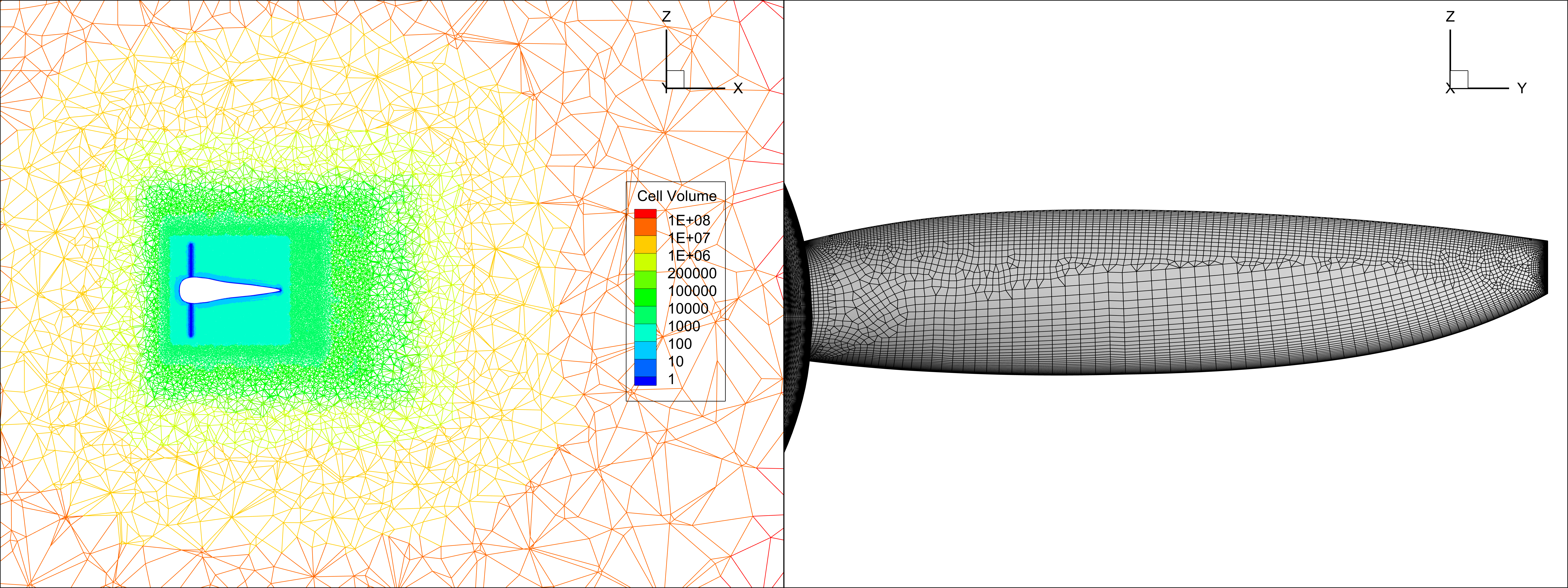
The FVM approach discretizes the simulation space into finite-sized volumetric elements. The points corresponding to each volumetric element define the underlying computational grid of the model. The resolution requirement of this grid depends on the local flow speeds and gradients affected by geometric features of the aircraft and rotor parts. Furthermore, the shear layers and vortices which populate the flow field are also taken into consideration while designing the computational grid.
Two example grids are shown below: one for the volume surrounding an isolated rotor simulation and the other for the surface of a rotor blade when the fully resolved model is applied. In the first figure, we have a finer grid resolution closer to the rotor disk and its wake region where velocities and their derivatives are expected to be higher. In the second example, the propeller blade has a denser grid resolution where sharp edges and highly curved features are present.

Since we are interested in performing a broad parameter study, involving several grid setups and different resolution requirements, we need to have a streamlined process for grid generation. Flow360 accomplishes this by directly taking in parametrically-defined geometry built with Engineering Sketch Pad (ESP) and automatically building the grid.
Due to the highly efficient architecture of Flexcompute’s Flow360 solver, we can model these different geometric and grid configurations at much lower computational cost than typically experienced.
This concludes PART II of the series. In the next and final article (PART III), we will present the results obtained from our parameter study campaign of this complex fluid dynamics problem. Stay tuned!
If you’d like to learn more about CFD simulations, how to optimize them, or how to reduce your simulation time from weeks or days to hours or minutes, stop by our website at Flexcompute.com or follow us on LinkedIn.
For the expanded version of the paper this content is derived from, see Impact of the Propulsion Modeling Approach on High-Lift Force Predictions of Propeller-Blown Wings.


